
Are you looking for an essay on ‘Magneto Hydro Dynamic Generation’? Find paragraphs, long and short essays on ‘Magneto Hydro Dynamic Generation’ especially written for school and college students.
Essay on Magneto Hydro Dynamic Generation
Essay Contents:
- Essay on the Introduction to Magneto Hydro Dynamic Generation
- Essay on the Principle of Magneto Hydro Dynamic Power Generation
- Essay on the Classification of Magneto Hydro Dynamic Generation Systems
- Essay on the Materials Used for Magneto Hydro Dynamic Generators
- Essay on the Voltage and Power Output of Magneto Hydro Dynamic Generator
- Essay on the Parameters Governing Power Output
- Essay on the Advantages and Disadvantages of Magneto Hydro Dynamic Systems
Essay # 1. Introduction to Magneto Hydro Dynamic Generation:
Magneto hydro dynamics is concerned with the flow of a conducting fluid in the presence of magnetic and electric fields.
MHD generator is a device which converts heat energy of fuel directly into electrical energy without a conventional electric generator.
i. MHD converter system is a heat engine whose efficiency, like all engines, is increased by supplying the heat at the highest practical temperature and rejecting it at the lowest practical temperature.
ii. MHD generation looks the most promising of the direct energy conversion techniques for large scale production of electrical energy.
Essay # 2. Principle of Magneto Hydro Dynamic Power Generation:
Faraday’s law of electromagnetic induction states:
“When a conductor and a magnetic field move in respect to each other, an electric voltage is induced in the conductor”.
The conductor need not be solid — it may be a gas or liquid.
MHD generator uses this principle by forcing a high-pressure high-temperature combustion gas through a strong magnetic field.
Fig. 9.9 shows the comparison between a turbo generator and the MHD generator:

Essay # 3. Classification of Magneto Hydro Dynamic Generation
Systems:
The broad classification of the MHD systems is as follows:
i. Open-cycle systems.
ii. Closed-Cycle Systems:
(i) Seeded inert gas systems
(ii) Liquid metal systems.
i. Open-Cycle MHD Systems:
Fig. 9.10 shows the schematic diagram of an open-cycle MHD system.

Construction and Working:
i. The fuel (e.g. Oil, coal, natural gas) is burnt in ‘combustion chamber’, air required for combustion is supplied from ‘air preheater’.
ii. The hot gas produced by the combustion chamber are then seeded with a small amount of an ionized alkali metal (cesium or potassium) to increase the electrical conductivity of the gas.
iii. The ionization of potassium (generally potassium carbonate is used as seed material) takes place due to gases produced at temperature of about 2300-2700°C by combustion.
iv. The hot pressurised working fluid so produced leaves the combustion chamber and passes through a convergent-divergent ‘nozzle’.
v. The gases coming out the nozzle at high velocity then enter the ‘MHD generator’.
vi. The MHD generator produces direct current (D.C.). By using an ‘inverter’ this direct current can be converted into alternating current (A.C.)
For efficient practical realization an MHD system must have following properties:
1. The combustion must have low heat losses.
2. Arrangement to add a low ionization potential seed material to the gas to increase its conductivity.
3. Air superheating arrangement to heat the gas to around 2500°C so that the electrical conductivity of the gas is increased.
4. Seed recovery apparatus — necessary for both environmental and economic reasons.
5. A magnet capable of producing high magnetic flux density (5 to 7 teslas).
6. A water cooled but electrically insulating expanding duct with long life electrodes.
ii. Closed-Cycle MHD Systems:
1. Seeded Inert Gas Closed-Cycle MHD System:
This MHD system works on Brayton cycle with inert carrier gas (Argon/helium). Refer to Fig. 9.11. In seeded inert gas system, electrical conductivity is maintained in the working fluid by ionization of a seed material. The inert gas is compressed and heated in primary heat exchanger.
Small quantity of seed material (e.g., cesium) is them added to make up for the loss of seed through leakage etc. At lower temperature, low cost seed material can also be a used but at low temperature, efficiency of the system reduces. The D.C. output from MHD generator is converted to A.C. in inverter.

2. Close-Cycle Liquid Metal MHD System:
Fig. 9.12 shows the schematic of a closed-cycle liquid metal system. In this system, a liquid metal (Potassium) is used as a working fluid.
 System")
Construction and Working:
i. The liquid potassium after being heated in the ‘breeder reactor’ is passed through the ‘nozzle’ where its velocity is increased.
ii. The vapours formed due to nozzle action are separated in the ‘separated and condensed and them pumped back to the reactor.
iii. Then the liquid metal with high velocity is passed through ‘MHD generator’ to produce D.C. power.
iv. The liquid possium coming out of MHD generator is passed through the heat exchanger’ (boiler) to use its remaining heat to run a turbine-generator set and then pumped back to the reactor.
The system entails many constructional and operational difficulties.
Essay # 4. Materials for MHD Generators:
Owing to high temperature of plasma (2700°C), refractory materials are required in various parts of MHD generator like electrodes, channel or duct wall.
The materials for various parts are given in Table 9.1 below:

Essay # 5. Voltage and Power Output of MHD Generator:
When a charged particle (having charge q) moving at a velocity v towards right is subjected to a perpendicular magnetic field (pointing into the paper), a magnetic force F acts on the charged particle (Fig. 9.13).
This force is given by:
![]()
Force F, velocity v and magnetic flux density B are vectors.


If an electric field E is also present in the region, the total force is:
![]()
The velocity to be used in the Eqn. (9.40) is the vector sum of gas velocity u and the particle drift velocity v.
Thus, force is given by:
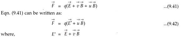
Refer to Fig. 9.14. The motion of the gas (v) is in ^-direction, magnetic field (B), is in the y-direct and the force (F) on the particle is in z-direction.
A resistance R (load) is connected between the two plates and current I flows> developing a voltage V across the load.
The electric intensity between the plates is:
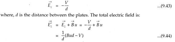
The electromagnetic field Ez and B acting on the moving gas produce the same force on the ions as the electromagnetic field E’z and B produce on a gas with zero average velocity. Evidently the open circuit voltage, E0 is;

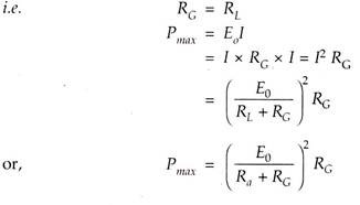
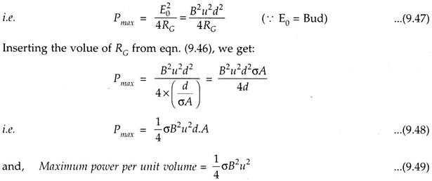
Maximum power output (Pmax) is obtained when:
Internal resistance = Load resistance
Essay # 6. Parameters Governing Power Output:
The parameters which govern the power output, for constant plate area and spacing are:
1. Gas Velocity:
The power output varies as square of the gas velocity, therefore it is advantageous to obtain as high a velocity as possible. This is achieved by converting thermal energy of the gas emerging from the furnace into direct kinetic energy. This conversion is carried out through the conventional nozzle expansion techniques.
It is possible to achieve velocities of the order of 1000 m/s.
2. Flux Density:
The power output also varies as square of magnetic flux density. In conventional magnets flux density upto 3 Wb/m2 can be obtained.
Magnets made of superconducting materials are being developed. With such magnets flux densities around 10 Wb/m2 can be obtained. The cost of the magnetic system of an MHD system is quite enormous.
3. Gaseous Conductivity:
The power output varies directly as conductivity. The gas must have a reasonable value of conductivity between 10 and 1000 mho/m to obtain a reasonable power output from MHD generator.
The conductivity can be increased by introducing a seeding material into the gas. The ionization potential of the seeding material is lower than that of gas atoms and thus this material ionizes more readily than the gas and increases the conductivity. ‘Cesium’ is the best seeding material having an ionization potential of 3.89 eV, but it is very costly. The next best is ‘Potassium’ which has an ionization potential of 4.34 eV.
Essay # 7. Advantages and Disadvantages of Magneto Hydro Dynamic Systems:
Advantages of Magneto Hydro Dynamic System:
1. More reliable since there are no moving parts.
2. In MHD system the efficiency can be about 50% (still higher expected) as compared to less than 40% for most efficient steam plants.
3. Power produced is free of pollution.
4. As soon as it is started it can reach the full power level.
5. The size of plant is considerably smaller than conventional fossil fuel plants.
6. Less overall operational cost.
7. The capital cost of MHD plants is comparable to those of conventional steam plants.
8. Better utilisation of fuel.
9. Suitable for a peak power generation.
Disadvantages of Magneto Hydro Dynamic System:
1. MHD systems suffer from the reverse flow (short circuits) of electrons through the conducting fluids around the ends of the magnetic field.
This loss can be reduced by:
(i) Increasing aspect ratio (L/D) of the generator,
(ii) By permitting the magnetic field poles to extend beyond the end of electrodes, and
(iii) By using insulated vanes in the fluid ducts and at the inlet and outlet of the generator.
2. There will be high friction losses and heat transfer losses. The friction loss may be as high as 12% of the input.
The MHD system operates at very high temperatures to obtain high electrical conductivity. But the electrodes must be relatively at low temperatures and hence the gas in the vicinity of the electrodes is cooler. This increases the resistivity of the gas near the electrodes and hence there will be a very large voltage drop across the gas film.
By adding the seed material, the resistivity can be reduced. The MHD system needs very large magnets and this is a major expense. Coal, when used as a fuel, poses the problem of molten ash which may short circuit the electrodes. Hence, oil or natural gas are considered to be much better fuels for this system. This restriction on the use of fuel makes the operation more expensive.