Are you looking for an essay on the ‘Classification of Solar Energy Storage System’? Find paragraphs, long and short essays on the ‘Classification of Solar Energy Storage System’ especially written for school and college students.
Classification of Solar Energy Storage System
Essay Contents:
- Essay on Solar Thermal Energy Storage System
- Essay on Thermo-Chemical Energy Storage System
- Essay on Electrical Storage System
- Essay on Electromagnetic Energy Storage System
- Essay on Mechanical Energy Storage System
Essay # 1. Solar Thermal Energy Storage System:
Thermal energy storage is the storage of energy by heating, melting or vaporisation of material and the energy becomes available as heat.
Thermal energy storage is of two types:
a. Sensible heat storage system.
b. Latent heat storage system.
a. Sensible Heat Storage System:
The storage by causing a material to rise in temperature is called sensible heat storage. It involves a material that undergoes no change in phase over the temperature domain encountered in the storage process. The quality of heat stored is proportional to the temperature rise of the material.
In a sensible heat storage system, energy is stored by heating a liquid or a solid.
In such a system the following materials are used:
Water; Inorganic molten salts and solids like rock, gravel, refractories, iron shot, concrete etc.
The choice of the material used depends on the temperature level of its utilisation (e.g. water is used for temperature below 100°C whereas refractory bricks can be used for temperatures up to 1100°C).
The basic equation(s) for an energy storage unit, operating over a finite temperature difference is:
where, Qs = The quantity of heat stored,
m = Mass of the storage material,
T1, T2 = The initial and final temperatures, respectively, and
cp = The specific heat of the storage material,
If V, p, cp are the volume, density and specific heat of the storage material, the energy storage (Qs) is given by:
Storage with Water:
The easiest way to store thermal energy is by storing the water directly in a well-insulated tank. For flat-plate collector system, the optimum tank size is usually about 70 kg/m2.
Following are the characteristics of water for storage medium:
(i) Inexpensive and readily available;
(ii) High thermal storage capacity;
(iii) Small pumping cost.
Storage with Packed Bed Exchange:
In this type of storage air is used as the energy transport mechanism; the storage materials used include rock, gravel or crushed stone in bin. Such materials provide a large and cheap heat transfer surface.
Water is superior because of its lower cost and lower volume required per unit of energy stored.
b. Latent (or Phase Change) Heat Storage:
In this system of heat storage, heat is stored in a material when it melts and extracted from the material when it freezes. Heat can also be stored when a liquid changes to gaseous state but as the volume change is large, such a system is not economical.
The following materials which melt on heating are suitable for solar energy applications:
(i) Organic Materials:
a. Paraffin wax- It has a high heat of fusion (209 kj/kg) and is known to freeze without inter cooling;
b. Fatty acids
(ii) Hydrated Salts:
a. Calcium chloride hexo hydrate (CaCl2.6H2O);
b. Sodium sulphate deca hydrate (Na2SO4.10H2O) – Glauber’s salt.
It melts at 32°C, with heat of fusion of 241 kJ/kg; the reaction is:
It has been proposed mainly for storing domestic heat.
(iii) Inorganic Materials:
b. Sodium nitrate (NaNO3);
c. Sodium hydroxide (NaOH).
Essay # 2. Thermo-Chemical Energy Storage System:
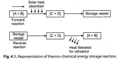
In this process, the heat of a chemical reaction is used to store thermal energy. Actually, the thermo-chemical thermal energy is the binding energy of reversible chemical reactions.
Fig. 4.1. shows the schematic representation of thermo-chemical energy storage reaction.
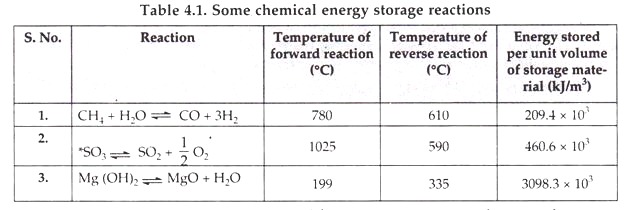
Table 4.1. Illustrates some chemical energy storage reactions.
This storage system has been suggested for use in 100 MW central tower solar power plant operating on Bray ton cycle with helium as the working fluid.
Chemical energy storage system, like latent heat storage system, has the advantage of releasing heat at “constant temperature”.
Essay # 3. Electrical Storage System:
i. Battery Storage:
A rechargeable storage battery (called secondary battery – a group of interconnected cells) receives electrical energy as direct current which is stored in the form of chemical energy by a reversible electro-chemical reaction.
The capacity of a battery is given in -terms of ampere-hours on discharge.
This is determined by the following factors:
(i) Final limiting voltage of the cells;
(ii) Discharge rate;
(iii) Number, design and dimensions of the plates;
(iv) Design of separators;
(v) Quantity of electrolyte;
(vi) Density of electrolyte;
(vii) Temperature etc.
The efficiency of a battery is defined as “the ratio of the output of battery to the input required to restore the initial state of charge under specified conditions of temperature, current rate and final voltage”.
Examples of secondary batteries are:
(i) Lead acid;
(ii) Nickel-cadmium;
(iii) Nickel-hydrogen,
(iv) Zinc-air;
(v) Sodium- sulphur etc.
The number of times the battery can be charged and discharged under specified conditions is called “Cycle life”. The cycle life of a battery may vary greatly with the depth of the discharge, deep discharge tending to result in short cycle life.
ii. Capacitor Storage:
In this storage process, the “capacitors” are used to store a large amount of electrical energy for fairly long periods.
The total energy stored is given by:
(Total energy stored)cap = 1/2 VεE2 …(4.4)
where, V = Volume of dielectric,
ε = Permittivity, a constant, and
E = Electric field strength.
The capacitors store electrical energy at high voltage and low current:
iii. Inductor Storage:
The energy stored by an inductor is given as:
(Total energy stored)Ind. = 1/2 VμB2
where, μ = Permeability of the material, and
B = Magnetic flux density.
The total energy stored will be high when both and B have large values; this will need high magnetic fields. This will create large mechanical forces which should be supported by strong structures. The reverse operation of discharging the stored energy entails the problem of opening of circuit carrying large currents.
The inductors store energy at low voltage and high current.
Essay # 4. Electromagnetic Energy Storage System:
In this process, the energy is stored in the magnetic field of a superconducting coil carrying direct current. By attaching the coil to a load, the stored energy could be recovered as electrical energy (direct current). This is basis of the Superconducting Magnetic Energy Storage (SMES) system.
Useful superconducting materials available commercially are:
(i) A niobium titanium (Nb – Ti) alloy at temperatures below -263°C, and
(ii) A compound of niobium and tin (Nb3Sn) below -255°C; these materials (metals and alloys) suddenly lose essentially all resistance to the flow of electricity when cooled below these very low temperatures.
Following problems are associated with superconducting storage:
1. The operation and maintenance of a cryogenic plant for producing the liquid helium required for the very low superconductivity temperatures.
2. Special structures are required to withstand the strong magnetic field of an SMES unit.
Essay # 5. Mechanical Energy Storage System:
i. Pumped Hydro-Electro Storage:
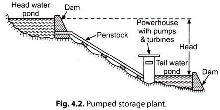
Refer to Fig. 4.2.
Pumped storage plants are employed at the places where the quantity of water available for power generation is inadequate. Here the water passing through the turbines is stored in ‘tail race pond’. During low load periods this water is pumped back to the head reservoir using the extra energy available.
This water can again be used for generating power during peak load periods. Pumping of water may be done seasonally or daily depending upon the conditions of the site and the nature of the load on the plant.
Such plants are usually interconnected with steam or diesel engine plants so that off peak capacity of interconnecting stations is used in pumping water and the same is used during peak load periods. Of course, the energy available from the quantity of water pumped by the plant is less than the energy input during pumped operation. Again while using pumped water the power available is reduced on account of losses occurring in prime movers.
ii. Compressed Air:
Compressed air energy storage follows the similar principles as pumped storage system. The excess electric energy generated by turbine during low loads can be stored by compressing the air in large vessels at high pressures. This energy can be utilised during peal hours of power requirement.
iii. Flywheel Storage:
When an electric motor, during its off peak hours, drives a flywheel, its speed is increased due to storage of mechanical (rotational) energy.
The basic idea of flywheel energy storage (sometimes known as ‘super flywheel’), is to accelerate a suitably designed physical rotor to a very high speed in a vacuum, as via electric motor, at which state high energy storage densities are achieved. The energy is stored as kinetic energy (K.E.), most of which can be electrically regained when the flywheel is run as a generator.


