Are you looking for an essay on ‘Gas Turbine Power Plants’? Find paragraphs, long and short essays on ‘Gas Turbine Power Plants’ especially written for school and college students.
Essay on Gas Turbine Power Plants
Essay Contents:
- Essay on the Introduction to Gas Turbine Power Plants
- Essay on the Site Selection for Gas Turbine Power Plants
- Essay on Energy Cycle for a Simple-Cycle Gas Turbine
- Essay on the Classification of Gas Turbine Power Plants
- Essay on the Combination Gas Turbine Cycles
- Essay on the Operation of a Gas Turbine Power Plants
- Essay on the Layout of Gas Turbine Power Plant
- Essay on the Performance of Diesel Engine in Gas Turbine Power Plant
- Essay on the Various Arrangements of Gas Turbine Power Plants
- Essay on the Advantages and Disadvantages of Gas Turbine Power Plants
- Essay on the Limitations of Gas Turbine Power Plants
- Essay on the Applications of Gas Turbine Plants
Essay # 1. Introduction to Gas Turbine Power Plants:
Probably a windmill was the first turbine to produce useful work, wherein there is no precompression and no combustion. The characteristic features of a gas turbine as we think of the name today include a compression process and a heat-addition (or combustion) process. The ‘gas turbine’ represents perhaps the most satisfactory way of producing very large quantities of power in a self-contained and compact unit.
The gas turbine may have an ample future use in conjunction with the oil engine. For smaller gas turbine units, the inefficiencies in compression and expansion processes become greater and to improve the thermal efficiency it is necessary to use a heat exchanger.
In order that a small gas turbine may compete for economy with the small oil engine or petrol engine it is necessary that a compact effective heat exchanger be used in the gas turbine cycle. The thermal efficiency of the gas turbine alone is still quite modest 20 to 30% compared with that of a modern steam plant 38 to 40%. It is possible to construct combined plants whose efficiencies are of the order of 45% or more. Higher efficiencies might be attained in future.
The following are the major fields of application of gas turbines:
i. Aviation.
ii. Power generation.
iii. Oil and gas industry.
iv. Marine propulsion.
The efficiency of a gas turbine is not the criteria for the choice of this plant. A gas turbine is used in aviation and marine fields because it is self contained, light weight not requiring cooling water and generally fit into the overall shape of the structure. It is selected for ‘power generation’ because of its simplicity, lack of cooling water, needs quick installation and quick starting. It is used in oil and gas industry because of cheaper supply of fuel and low installation cost.
Essay # 2. Site Selection for Gas Turbine Power Plant:
While selecting the site for a gas turbine plant the following points should be given due consideration:
1. The plant should be located near the load centre to avoid transmission costs and losses.
2. The site should be away from business centres due to noisy operations.
3. Cheap and good quality fuel should be easily available.
4. Availability of labour.
5. Availability of means of transportation.
6. The land should be available at a cheap price.
7. The bearing capacity of the land should be high.
Essay # 3. Energy Cycle for a Simple-Cycle Gas Turbine:
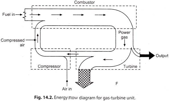
Fig. 14.2 shows an energy-flow diagram for a simple-cycle gas turbine, the description of which is as follows:
i. The air brings in minute amount of energy (measured above 0°C).
ii. Compressor adds considerable amount of energy.
iii. Fuel carries major input to cycle.
iv. Sum of fuel and compressed-air energy leaves combustor to enter turbine.
v. In turbine smallest part of entering energy goes to useful output, largest part leaves in exhaust.
Shaft energy to drive compressor is about twice as much as the useful shaft output.
Actually the shaft energy keeps circulating in the cycle as long as the turbine runs. The important comparison is the size of the output with the fuel input. For the simple-cycle gas turbine the output may run about 20 per cent of the fuel input for pressure and temperature conditions at turbine inlet. This means 80% of the fuel energy is wasted. While the 20% thermal efficiency is not too bad, it can be improved by including additional heat recovery apparatus.
Essay # 4. Classification of Gas Turbine Power Plants:
The gas turbine power plants may be classified according to the following criteria:
1. By application:
(i) In aircraft:
(a) Jet propulsion
(b) Prop-jets
(ii) Stationary:
(a) Peak load unit
(b) Standby unit
(c) End of transmission line unit
(d) Base load unit
(e) Industrial unit.
(iii) Locomotive
(iv) Marine
(v) Transport.
2. By cycle:
(i) Open cycle
(ii) Closed cycle
(iii) Semi-closed cycle.
3. According to arrangement:
(i) Simple
(ii) Single shaft
(iii) Multi-shaft
(iv) Intercooled
(v) Reheat
(vi) Regenerative
(vii) Combination.
4. According to combustion:
(i) Continuous combustion
(ii) Intermittent combustion.
5. By fuel:
(i) Solid fuel
(ii) Liquid fuel
(iii) Gaseous fuel.
Essay # 5. Combination Gas Turbine Cycles:
The characteristics of the gas turbine plants render these plants very well suited for use in combination with steam or hydro-plants. These plants can be quickly started for emergency or peak load service. The combination ‘gas-turbine-steam cycles’ aim at utilising the heat of exhaust gases from the gas turbine and thus, improve the overall plant efficiency.
Three popular designs of combination cycle comprise of:
1. Heating feed water with exhaust gases.
2. Employing the gases from a supercharged boiler to expand in the gas turbine.
3. Employing the gases as combustion air in the steam boiler.
1. Heating feed water with exhaust gases:
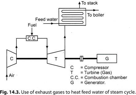
Refer to Fig. 14.3. By employing exhaust gases to heat the feed water it is possible to utilise the entire steam supply to the turbines to expand through entire range of expansion, and thus result in increasing the output of work, since bleeding would not be required.
2. Employing the gases from a supercharged boiler to expand in the gas turbine:
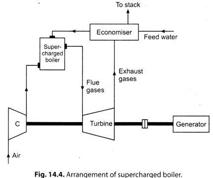
Refer to Fig. 14.4. The supercharged boiler is good application of the combined gas turbine-steam cycle. In this arrangement the boiler furnace works under a pressure of about 5 bar and the gases are expanded in the gas turbine, its exhaust being used to heat feed water before being discharged through the stack.
The heat transfer rate in this boiler is very high as compared to that in a conventional boiler due to higher pressure of gases; and a smaller size of steam generator is needed for the same steam raising capacity as of the conventional plant.
Furthermore, since the gases in the furnace are already under pressure, no induced draught or forced draught fans are needed and there is saving in power consumption which would otherwise be spent in mechanical draught supply. Through this combination an overall improvement in heat rate is to the extent of above 7 percent.
3. Employing the gases as combustion air in the steam boiler:
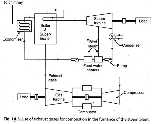
Refer to Fig. 14.5. When exhaust gases are used as preheated air for combustion in the boiler, an improvement of about 5 percent in overall heat rate of the plant results. The boiler is fed with supplementary fuel and air, and is made larger than the conventional furnace. If only the turbine exhaust is used in the furnace without any supplementary fuel firing, the arrangement becomes a waste heat boiler.
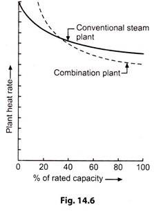
i. Fig. 14.6 shows the gain in heat rate due to combination cycle.
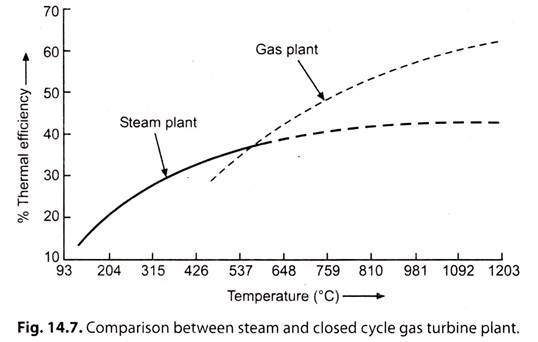
ii. Fig. 14.7 shows the comparison of a steam and closed cycle gas plant.
Essay # 6. Operation of a Gas Turbine Power Plants:
The operation of a gas turbine includes the following:
1. Starting.
2. Shut down.
1. Starting of a gas turbine:
Starting of a gas turbine power plant requires an auxiliary power source, till the plant’s own compressor inducts air and compresses it to a pressure such that expansion from reasonable temperature will develop enough power to sustain operation.
The starter may be:
(i) An I.C. engine
(ii) A steam turbine
(iii) An auxiliary electric motor or
(iv) another gas turbine.
It must be coupled to the turbo-compressor shaft with a disengaging or over-running clutch. A main generator or its direct connected exciter may be pressed into temporary service as a motor.
Starting procedure:
1. Run the unit and induct air.
2. Actuate the combustion ignition system and inject the fuel. The fuel flow is controlled to obtain the necessary warm up.
3. Adjust the speed and voltage and synchronise the alternator.
4. Build up the load on the alternator by governor gear control.
2. Shut down of a gas turbine:
Shut down of a gas turbine occurs very quickly after the fuel is cut off from the combustor. A rapid shut down is desirable since it minimizes the chilling effect resulting from passing cold air through the hot turbine. Turning gears are usually employed, or alternatively the starting device may be operated at reduced speed to ensure symmetrical cooling of rotor. This avoids thermal ‘kinking’ of the shaft.
Essay # 7. Layout of
Gas Turbine Power Plant:
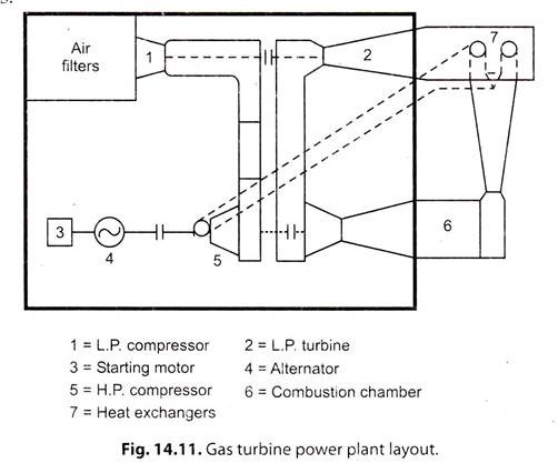
The layout of a gas turbine plant exercises a very important effect on the overall performance of the plant, as it is possible to incur a loss to the extent of 20% of the power developed in the interconnecting ducts having a considerable number of sharp bends. Therefore ample care should be taken in the design and layout of the air as well as gas circuits. Fig. 14.11 shows a schematic simplified diagram of a gas turbine power plant layout.
The following points are worth noting:
i. In this case the main building is the turbine house in which major portion of the plant as well as auxiliaries are installed. Usually it is similar to the steam plant house in many respects.
ii. The storage tanks containing fuel oil are arranged outside but adjoining the turbine house. In some installations even heat exchangers are also out of the doors.
Whereas the major portion of the total space is occupied by the intercoolers, combustion chambers, heat exchangers, waste heat boilers and interconnecting duct work, the rotating parts of the plant form a very small part of the total volume of the plant.
Essay # 8. Performance of Diesel Engine in Gas Turbine Power Plants:
Improving the performance of a diesel engine:
The performance of a diesel engine can be improved by combining it with an exhaust driven gas turbine.
It can be achieved by the following three combinations:
1. Turbo-charging.
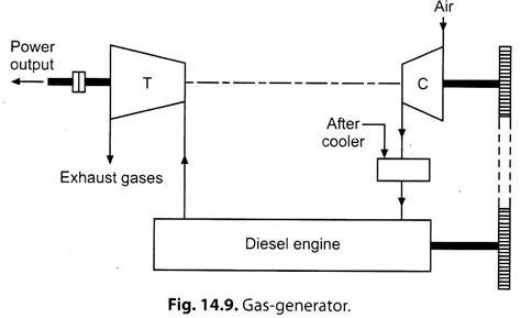
2. Gas-generator.
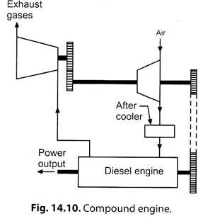
3. Compound engine.
1. Turbo-Charging:
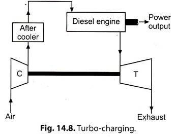
Refer to Fig. 14.8. This method is known as supercharging. Here the exhaust of the diesel engine is expanded in the gas turbine and the work output of the gas turbine is utilised to run a compressor which supplies the pressurised air to the diesel engine to increase its output. The load is coupled to the diesel engine shaft and the output of the gas turbine is just sufficient to run the compressor.
2. Gas-Generator:
Fig. 14.9 shows the schematic arrangement. Here the compressor which supplies the compressed air to the diesel engine is not driven from gas turbine but from the diesel engine through some suitable drive. The output of the diesel engine is consumed in driving the air compressor and the gas turbine supplies the power.
3. Compound engine:
Refer to Fig. 14.10. In this arrangement the air compressor is driven from both diesel engine and gas turbine through a suitable gearing and the power output is taken from the diesel engine shaft.
Essay # 9. Various Arrangements of Gas Turbine Power Plants:
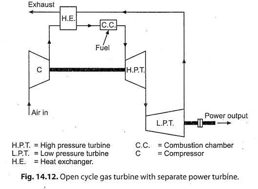
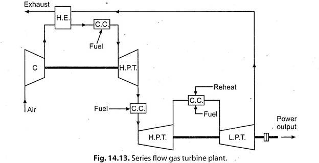
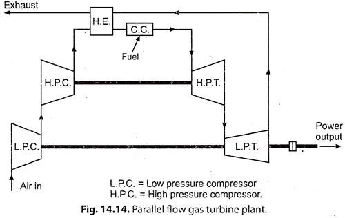
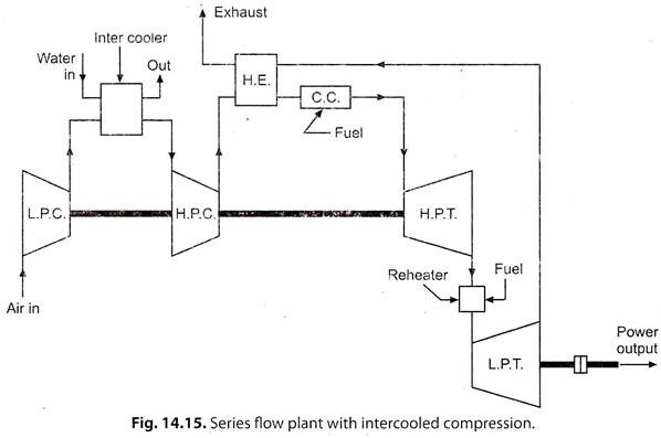
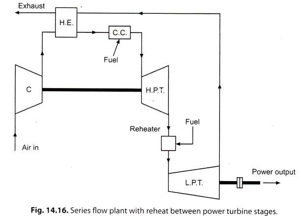
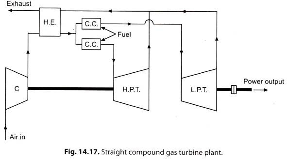
The various arrangements of gas turbine plants are shown in Figs. 14.12 to 14.17.
Essay # 10. Advantages and Disadvantages of Gas Turbine Power Plants:
A. Advantages over diesel plants:
1. The work developed per kg of air is large compared with diesel plant.
2. Less vibrations due to perfect balancing.
3. Less space requirements.
4. Capital cost considerably less.
5. Higher mechanical efficiency.
6. The running speed of the turbine (40,000 to 100,000 r.p.m.) is considerably large compared to diesel engine (1000 to 2000 r.p.m.).
7. Lower installation and maintenance costs.
8. The torque characteristics of turbine plants are far better than diesel plants.
9. The ignition and lubrication systems are simpler.
10. The specific fuel consumption does not increase with time in gas turbine plant as rapidly as in diesel plants.
11. Poor quality fuels can be used.
Disadvantages:
1. Poor part load efficiency.
2. Special metals and alloys are required for different components of the plants.
3. Special cooling methods are required for cooling the turbine blades.
4. Short life.
B. Advantages over steam power plant:
1. No ash handling problem.
2. Low capital cost.
3. The gas turbine plants can be installed at selected load centre as space requirement is considerably less where steam plant cannot be accommodated.
4. Fewer auxiliaries required /used.
5. Gas turbines can be built relatively quicker. They require much less space and civil engineering works and water supply.
6. The gas turbine plant as peak load plant is more preferable as it can be brought on load quickly and surely.
7. The components and circuits of a gas turbine plant can be arranged to give the most economic results in any given circumstances which is not possible in case of steam power plants.
8. For the same pressure and initial temperature conditions the ratio of exhaust to inlet volume would be only 3.95 in case of gas turbine plant as against 250 for steam plant.
9. Above 550°C, the thermal efficiency of the gas turbine plant increases three times as fast the steam cycle efficiency for a given top temperature increase.
10. The site of the steam power plant is dictated by the availability of large cooling water whereas an open cycle gas turbine plant can be located near the load centre as no cooling water is required. The cooling water required for closed cycle gas turbine is hardly 10% of the steam power plant.
11. The gas turbine plants can work quite economically for short running hours.
12. Storage of fuel is much smaller and handling is easy.
Essay # 11. Limitations of Gas Turbine Power Plants:
The gas turbines have the following “limitations”:
1. They.are not self starting.
2. Low efficiencies at part loads.
3. Non-reversibility.
4. Higher rotor speeds.
5. Low overall plant efficiency.
In the last two decides, rapid progress has been observed in the development and improvement of the gas turbine plants for electric power production.
The major progress has been observed in the following directions:
(i) Increase in unit capacities of gas turbine units.
(ii) Increase in their efficiency.
(iii)Drop in capital cost.
Essay # 12. Applications of Gas Turbine Plants:
Gas turbine plants for the purpose of power plant engineering find the following applications:
i. To drive generators and supply peak loads in steam, diesel or hydroplants:
These plants are well suited for peak load service since the fuel costs are somewhat higher and initial cost low. Moreover, peak load operation permits use of water injection which increases turbine work by about 40% with an increase in heat rate of about 20%. The short duration of increase in heat rate does not prove of any much harm.
ii. To work as combination plants with conventional steam boilers:
The combination arrangement of gas turbines with conventional boilers may be supercharging or for heat recovery from exhaust gases. In the supercharging system air is supplied to the boiler under pressure by a compressor mounted on the common shaft with turbine, and gases formed as result of combination after coming out of the boiler pass through the gas turbine before passing through the economiser and the chimney.
iii. To supply mechanical drive for auxiliaries:
The application of the gas turbine to drive the auxiliaries is not strictly included under direct electric power generation by the turbines.
