
Are you looking for an essay on ‘Fuel Cells’? Find paragraphs, long and short essays on ‘Fuel Cells’ especially written for school and college students.
Essay on Fuel Cells
Essay Contents:
- Essay on the Introduction to Fuel Cells
- Essay on the Components and Working Theory of a Fuel Cell
- Essay on the Types of Fuels Used in Fuel Cells
- Essay on the Desirable Characteristics of a Fuel Cell
- Essay on the Classification of Fuel Cells
- Essay on the Performance Analysis of a Fuel Cell
- Essay on Fuel Cell Power Plant
- Essay on the Advantages and Disadvantages of Fuel Cells
- Essay on the Applications of Fuel Cells
Essay # 1. Introduction to Fuel Cells:
A fuel cell is an electrochemical device in which the chemical energy of a conventional fuel is converted directly and efficiently into low voltage, direct current electrical energy.
i. Fuel cell systems generally operate on pure hydrogen and air to produce electricity.
ii. One of the chief advantages of such a device in that because the conversion, at least in theory, can be carried out isothermally, the Carnot limitation on efficiency does not apply.
iii. The essential difference between the primary/secondary cell and fuel cell is of continuous energy input and output of fuel cell. A fuel cell system requires continuous supply of a fuel and an oxidizer and generates D.C. electric power continuously.
iv. A battery has stored electrochemical energy within its container. After discharge it needs recharging or replacement. Fuel cells do not need such recharging replacement. A fuel cell is often described as a primary battery in which the fuel and oxidize are stored external to the battery and fed to it as needed.
v. Fuel cells can be manufactured as large or as small as necessary for the particular power application. Presently, there are fuel cells that are the size of a pencil eraser and generate few milliwatts of power while there are others large enough to provide large amount of power. The power output of fuel cells is fully scalable by varying the cross-sectional area of each cell to get desired current and by stacking multiple cells in series to obtain the desired voltage.
Note:
The first fuel cell was developed in 1839 in England by Sir William Grove. However, the application of fuel cell was first demonstrated by Francis T. Bacon in 1959 when his model generated 5kW at 24V. Its practical application began during the 1960s when the US space programme chose fuel cells over nuclear power and solar energy. Fuel cells provided power to the Gemini, Apollo and Skylab spacecraft; continue to be used to provide electricity and water to space shuttles.
Essay # 2. Components and Working Theory of a Fuel Cell:
Components of a Fuel Cell:
The main components of a cell are:
1. Anode (Fuel electrode)
2. Cathode (oxidant electrode)
3. Electrolyte
4. Container
5. Separators
6. Sealings
7. Fuel supply
8. Oxidizer.
Working Theory of a Fuel Cell:
Fig. 9.16 shows a schematic diagram of a fuel cell.
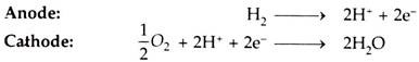
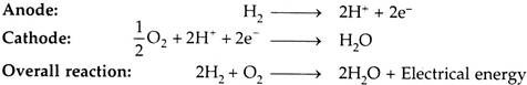
The ‘fuel gas’ diffuses through the anode and is oxidized, thus releasing electrons to the external circuit.
The ‘oxidizer’ diffuses through the cathode and is reduced by the electrons that have come from the anode by way of the external circuit.

The fuel cell is a device that keeps the fuel molecules from mixing with the oxidizer molecules, permitting, however, the transfer of electrons by a metallic path that may contain a load.
Of the available fuels, hydrogen has so far given the most promising results, although cells consuming coal, oil or natural gas would be economically much more useful for large scale applications.
Some of the possible reactions are:
![]()
![]()
Essay # 3. Types of Fuels Used in Fuel Cells:
The following fuels are mostly used in fuel cells:
1. Hydrogen (H2).
2. Hydrocarbon fuels.
3. Fossil fuel.
4. Alcohol fuel.
5. Hydrazine (N2H4) fuel.
Essay # 4. Desirable Characteristics of a Fuel Cell:
The fuel cell should have the following characteristics:
1. It should have high energy conversion efficiency.
2. It should produce low chemical pollution.
3. It should be flexible to choose any fuel.
4. It should have cogeneration capability and rapid load response.
Essay # 5. Classification of Fuel Cells:
Fuel cells may be classified as follows:
A. Based on Operating Temperature:
i. Low temperature fuel cell 25-100°C.
ii. Medium temperature fuel cell (below 100-500°C).
iii. High temperature fuel cell (500-1000°C).
iv. Very high temperature fuel cell (Above 1100°C).
B. Based on the Type of Electrolyte:
i. Alkaline fuel cell (AFC).
ii. Phosphoric acid fuel cell (PAFC).
iii. Polymer electrolytic membrane fuel cell (PEMFC).
iv. Molten carbonate fuel cell (MCFC).
v. Solid oxide fuel cell (SOFC).
i. Hydrogen-Oxygen Fuel Cell (Hydrox Cell)-Alkaline Fuel Cell (AFC):
In this cell hydrogen and oxygen are used as the ‘fuel’ and ‘oxidant’ respectively as these elements are most reactive with least complications. The ‘electrolyte’ is potassium hydroxide (20 to 40% concentration) which has high electrical conductivity and is less corrosive than acids.
Fig. 9.17 shows structure of a hydrox cell (alkaline cell).
 Fuel Cell")
Construction:
It has three chambers separated by two porous nickel electrodes, the anode and cathode. The middle chamber between the electrodes is filled with a strong solution of potassium hydroxide (KOH). The surfaces of the electrodes are chemically treated to repel the electrolyte, so that there is minimum leakage of potassium hydroxide into the outer chamber.
Working:
The gases diffuse through the electrodes, undergoing reactions as shown below:

The electrons so produced build up a negative potential and move towards the cathode through an externally connected circuit.
Cathode:
At cathode, the electrons are picked up by oxygen atoms available there, react with water present in the electrolyte to form hydroxide (OH)– ions, the reaction being:
![]()
(OH)– ions combine with hydrogen ion (H+) to form water as per the following reactions,

The water formed is drawn off from the side.
The electrolyte provides the (OH)– ions needed for the reaction, and remains unchanged at the end, since these are regenerated. The electrons liberated at the anode find their way to the cathode through the external circuit. This transfer is equivalent to the flow of current from the cathode to anode.
i. Such cells when properly designed and operated, have an open circuit voltage of about 1.1V. Unfortunately, their life is limited since the water formed continuously dilutes the electrolyte. The working temperature is 90°C. Fuel efficiencies and high as 60 to 70% may be obtained.
ii. When pure H2 and O2 reactants are available, as in rocket and spacecraft, there is no fuel cell that can compete with the high power densities offered by alkaline fuel cells (AFCs).
iii. The Low-temperature cell and High-pressure cell are typical developments of the hydrogen-oxygen cell.
Applications:
In space and military works.
ii. Phosphoric Acid Fuel Cell (PAFC):
Fig. 9.18 shows a phosphoric acid (H3PO4) cell.

The phosphoric acid cell consists of two electrodes of porous conducting material (e.g. nickel) to collect charge and, ‘phosphoric acid’ used as electrolyte.
At anode, hydrogen molecule is split into hydrogen ions (protons) and electrons. The electrons flow through external circuit and produce electric power while protons travel through electrolyte and combine with oxygen, usually from air, at the cathode to form water.
The electrochemical reaction is very slow, so a catalyst is required in the electrode to accelerate the reaction. The catalysts used are platinum, nickel (for anode) and silver (for cathode). Platinum is the best catalyst for both electrodes.
Reactions in this fuel cell produce electricity and by-product heat.
The reactions are given below:
Overall Cell Reaction:
![]()
At atmospheric pressure PAFC produces an ideal emf of 1. 23V at 25°C which reduces to 1.15 V at operating temperature between 150 to 200°C.
Application:
These cells are used commercially having the plant capacity in the range of 50 kW to 200 kW.
iii. Polymer Electrolyte Membrane Fuel Cell (PEMFC):
Fig. 9.19. illustrates a polymer electrolyte membrane fuel cell.
")
In PEMFC cell, electrolyte is a solid polymer membrane of an organic material such as polystyrene sulphonic acid and this is permeable to protons (H+) when it is saturated with water but it does not conduct electrons.
The fuel is hydrogen and charge carriers are hydrogen ions (protons). At the anode, the hydrogen molecule is split into hydrogen ions and electrons. The hydrogen ions permeate across the electrolyte to cathode while the electrons flow through an external circuit and produce electric power. Oxygen is supplied to the cathode and combines with electrons and hydrogen ions to produce water.
The reactions at anode and cathode are given below:
The membrane is coated on both sides with finely powdered platinum which acts as a catalyst.
This cell are also called “Ion-exchange membrane cell”.
The desired properties of the electrolyte of an ideal ion-exchange membrane cell:
(i) Low permeability of fuel and oxidants.
(ii) High ionic conductivity.
(iii) Zero electronic conductivity.
(iv) Low degree of electro-osmosis.
(v) Mechanical stability.
(vi) High resistance to hydration.
(vii) High resistance to the oxidation or hydrolysis.
Applications, Residential, portable laptops, cellular phones, video cameras, buses, cars, railway locomotives.
iv. Molten Carbonate Fuel Cell (MCFC):
This type of cell uses an electrolyte, which is a molten mixture of carbonate salts.
Two mixtures commonly used are:
(i) Lithium carbonate and potassium carbonate, and
(ii) Lithium carbonate and sodium carbonate.
Since these salts can act as electrolytes only in liquid phase, the operating temperature should as high as 650°C. Fig. 9.20 shows the MCFC in which porous nickel is used as electrodes and electrolyte is held in a spong like ceramic matrix.
")
A hydrocarbon fuel, such as methane or kerosene, is used. The fuel is reacted inside the cell to produce H2O and CO. At the fuel electrode (anode) H2O and CO react with CO3 ions in the electrolyte, releasing electrons to the electrode, and forming H2O and CO2. At the oxygen electrode O2 reacts with the returning electrons and CO2 diverted from the fuel electrode to form CO3 ions. These CO3 ions then migrate through the electrolyte to the fuel rod.
The reactions are given below:

These released electrons circulate through external resistance (load), forming load current and reach at oxygen electrode (cathode).
![]()
The CO3— ions are responsible for transportation of charge from cathode to anode within the electrolyte.
Overall Reaction:
![]()
The theoretical e.m.f. produced by each cell is 1 V and actual e.m.f. being 0.8 V at 700° C. The expected efficiency is about 60%.
Applications. Dispersed power and utility power.
v. Solid Oxide Fuel Cell (SOFC):
Fig. 9.21 Illustrates a solid oxide fuel cell (tubular shape).
")
i. This cell is based on a solid metal oxide ‘electrolyte’ (zirconium dioxide) called zirconia. It allows ionic conductivity of oxygen ions from cathode to anode. The electrodes are electric conductors with a high porosity. The operating temperature (800-1000°C) is high enough for internal reforming of natural gas in the anode chamber. The water gas shift reaction takes place at the anode, thus enabling H2 and CO mixtures to be used as fuel feedstock.
ii. The construction materials used are metal oxides and ceramics. The central hollow space is for air flow that acts as an oxidant. Its operation is efficient at 1000°C and 1 atmospheric pressure.
iii. Fuel gas flows through the outermost layer of the fuel electrode. Next to it is the electrolyte layer. The fuel gas permeates through the porous electrodes and is oxidized by air containing oxygen. The air electrode is next to electrolyte and air flows axially through the central hollow space.
iv. Both fuel gas and oxidant are fed into the cell continuously which gets consumed and the cell delivers electrical energy.
The solid oxide fuel cell fueled by natural gas can attain a high electrical efficiency upto 55 percent. Each cell delivers 25 A current at 0.7V and a pack of 50 fuel cells give an output of 1 kW.
These cells promise a vast potential in utilisation of low grade high ash, graded coals through Fluidized Bed Gasification.
Applications:
Domestic and commercial utility power; mobile applications for railways.
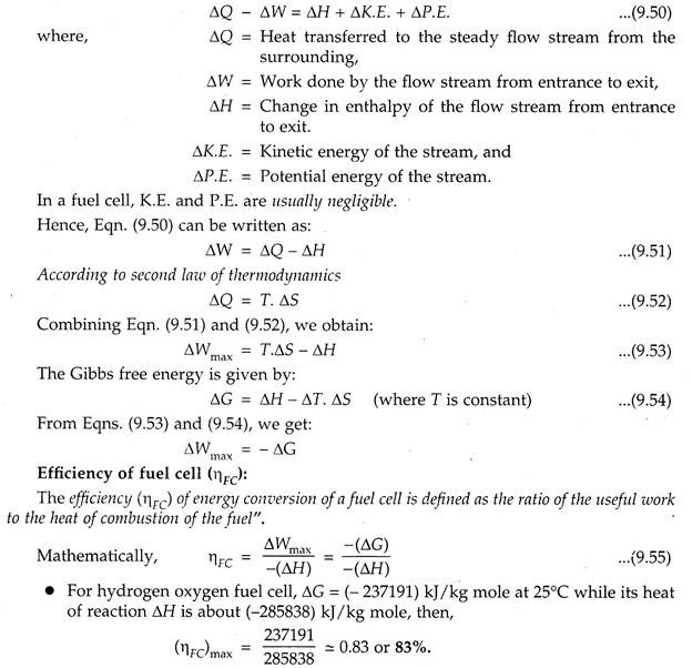
Essay # 6. Performance Analysis of a Fuel Cell:
In a fuel cell, a chemical reaction takes place where the reactants are converted into products in a steady flow process.
The work is obtained by combining the first and second laws of thermodynamics for a steady flow process as follows:
For a steady flow process, according to the first law of thermodynamics,
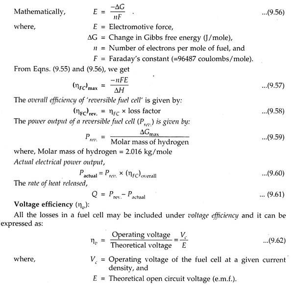
V.I and P.I. Characteristics of a Fuel Cell:
The various characteristics of a fuel cell are:
1. Current-voltage (V-I) characteristics.
2. Power-current (P-I) characteristics.
1. Current-Voltage (V-I) Characteristics:
The performance of a fuel cell is evaluated by the cell voltage Vc versus electrode current density ld curve (Fig. 9.22). Vc drops with increase in Id due to ‘polarization’ within the cell. Hence, the curve is also called the polarization curve of the fuel cell.
Polarisation is internal, chemical, electrical, thermal effects within the fuel cell resulting in inefficiencies. Polarization, the cause of internal energy loss, is measured in terms or polarization voltage Vp.
ΔVp = E-Vc …(9.63)

With increase in load of the cell, the internal losses increase, resulting in the drop of cell terminal voltage (Vc).
2. Power-Current (P-I) Characteristics:
Power per cell, Pc = Vc x IC …(9.64)
The power of a cell increases with the increase in current density till saturation point is reached; thereafter it decreases due to polarization effects.
Output power = Input power – polarization losses Now, Efficiency of fuel cell,

Fig. 9.23 shows the power and efficiency characteristics of a fuel cell.

i. The efficiency of a fuel cell varies with the current density at electrode surface due to the polarization effect.
ii. The power loss is converted to waste heat and released to atmosphere.
Example:
A hydrogen-oxygen cell operates at 25°C.
Given: ΔH°298K = – 285838 kJAg mole., ΔG°298k = -237191 kJ/kg mole, and molar mass of hydrogen = 2.016.
Calculate:
(i) Efficiency of the fuel cell.
(ii) Electrical work output per mole H2 consumed and per mole of HzO produced.
(iii) Heat transfer to the surroundings.
Solution:
Given: T = 25 + 273 = 298 K; ΔH°298 = -285838 kj/kg mole; ΔG°298K = 237191 kJ/kg mole.
(i) Efficiency of the fuel cell, ηFC:
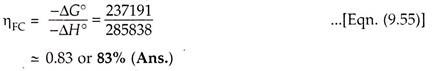
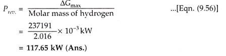
(ii) Electrical work output/mole of H2O produced, Prev:
(iii) Heat transfer to the surroundings, Q:
Q = T ΔS= (AH°)298K – (AG°)298K …(Eqn. (9.54))
= – 285838 – (237191) = – 48647 kj/kg mole (Ans.)
The -ve sign indicates that heat is transferred from the system to surroundings.
Essay # 7. Fuel Cell Power Plant:
The primary fossil fuels are used to generate electrical energy in fuel cell power plant.
Fig. 9.24. shows the schematic of fuel cell based electrical power generation scheme:

i. The fossil fuel is supplied to the ‘fuel processing unit’, where fuel is purified and then supplied to ‘fuel cell modules’.
ii. The fuel cell modules convert fuel energy electrochemically into D.C. power.
iii. A number of fuel cells are stacked to form a module and several modules are interconnected to form a power producing unit.
iv. The power conditioning unit converts D.C. output to A.C output using ‘inverter’; and the standard rated supply being 3-phase, 400 V, 50 Hz/60 Hz or single phase, 230 V/110 V, 50 Hz/60Hz.
Modules of size 200-250 kW are commonly available.
Advantages of Fuel Cell Power Plants:
Following are the advantages of fuel cell power plants:
1. Besides electric power, fuel cell plants also supply hot water, space heat and steam.
2. These plants are eco-friendly and noiseless (since they don’t have rotating parts.)
3. Fuel cell plants can attain high efficiency upto 55%, whereas conventional thermal plants operate at around 30% efficiency.
4. These plants have cogeneration capabilities.
5. A large degree of modularity is available with capacity ranging from 5 kW to 25 MW.
6. There is a wide choice of fuels for fuel cells.
7. It is a decentralised plant, can be operated in isolation for military installations and hospitals where noise and smoke are prohibited.
Essay # 8. Advantages and Disadvantages of Fuel Cells:
Following are the advantages, disadvantages and applications of fuel cells:
Advantages of Fuel Cells:
1. Conversion efficiencies are high.
2. Require little attention and less maintenance.
3. Can be installed near the use point, thus reducing electrical transmission requirements and accompanying losses.
4. Fuel cell is odourless and does not make any noise.
5. A little time is needed to go into operation.
6. Space requirement considerably less in comparison to conventional power plants.
7. Simple and safe.
8. Pollution free.
9. No cooling water needed.
10. Capacity can be increased as the demand grows.
11. Long life.
Disadvantages of Fuel Cells:
1. High initial cost.
2. Low service life.
3. Problems for refilling in vehicles.
Essay # 9. Applications of Fuel Cells:
The applications of fuel cell relate to:
1. Domestic use.
2. Automotive vehicles.
3. Central power stations.
4. Defence applications.
5. Space projects.
Fuel cells are primarily suited for low voltage and high current applications.