
Are you looking for an essay on the ‘Types of Hardware’? Find paragraphs, long and short essays on the ‘Types of Hardware’ especially written for school and college students.
Essay on the Hardware
Essay Contents:
- Essay on the Central Processing Unit—CPU
- Essay on the Main Memory
- Essay on Magnetic Core and Bubble Storage
- Essay on Addressing System
- Essay on Input Device
- Essay on Output Device
- Essay on Secondary Storage
Essay # 1. Central Processing Unit—CPU:
CPU is the heart and soul of the computer system which controls everything whether it is input of data, processing in different ways, storage and retrieval using secondary storage, or output through different devices.
It dictates each part to do their respective assigned roles, which reports back on completion. For example, if some document is to be printed, it checks whether the printer is ready to receive the material, and being satisfied, sends the information to the printer.
If the paper gets exhausted, it gets feedback from the printer and displays such message—of course, everything is done by it under different sets of instructions. In modern computers, the Central Processing Unit is housed in the microprocessor chip or simply, the chip; which is broadly divided into two sections called Control Section and Arithmetic-Logic Unit [ALU].
What the control section basically does is, it fetches an instruction from a specific-location in the main-memory (primary storage) to a specific location inside it called a Register, decodes the instruction to understand what it has to do, and then executes it by sending commands to different parts to do the specific task—which may be getting a data for computation from memory to the register called Accumulator within the ALU, or moving a data from one place to another in the memory or from a disk to memory, or performing some arithmetical computation or some logical operation, and so on.
All these are done by changing the settings of switches by making some bits on or off. After an instruction is executed, again the fetch-decode-execute cycle continues with the next instruction and this continues until all the instructions are executed; if nothing goes wrong.
In these operations, Registers are extensively used which are special storage places within the Central Processing Unit, and used for temporarily storing data, instruction, information and addresses during program execution. The registers are identified by their specific names like say, AX, BX, CS, DS, etc. of 8088 chips. A specific register which is mostly used in arithmetical computation is called Accumulator.
The operations performed in the Arithmetic-Logic Unit are the arithmetic computations and logical operations called AND, OR, XOR, NOT, etc. and for this purpose, there are different circuit elements called Logic Gates. These logic gates help us to write instructions incorporating decision making options, as stated at the very beginning.
For example, we may say that subtract B from A if A is greater than B, else subtract B from A—where a decision has to be taken. The ALU also contains, among others, a special circuit which carries out the process of addition of the values, generally available in Registers, the circuit being called Adder. Similarly, there are Shifters and Counters.
All the activities inside the CPU are synchronized by a clock which creates train of pulses of 0s and 1s. This clock frequency, given by number of cycles per second, is expressed in Megahertz and was 4.77 Megahertz in the first Personal Computer.
The clock speed gives a relative indication of speed of operation between different computers. The timing of each operation carried out under the control of the Control Section is decided by these clock pulses.
The time required to fetch an instruction is called Fetch Cycle and that required to execute an instruction is called Execute Cycle. Naturally these vary between chips of different designs and are also dependent on the clock speed used.
The combined time required to fetch and execute an instruction is called Instruction Cycle. Each Instruction Cycle requires different Clock Cycles to execute, depending on what the instruction does.
Essay # 2. The Main Memory:
The main memory or the primary storage uses semiconductor elements, which are of different types. The main portion is called RAM, or Random Access Memory, which is a memory of the type which can be read or written randomly at any location. These are of Metal Oxide Type [MOS]. This is also of volatile type, that is, when the power is switched off, all that is stored in the RAM is lost.
The other type of memory elements used in the main memory is called ROM, or Read Only Memory. The data or instructions stored on this type can only be read but cannot be overwritten and is not lost when the power is switched off— it is of non-volatile type.
The Basic Input Output System, called BIOS, which executes when the computer is switched on and provides many other valuable services, is stored in ROM and hence called, ROM BIOS.
The RAM chips are of two types, classified as Dynamic and Static RAMs. The basic difference is that whatever is stored in Dynamic RAM gets lost with time and needs to be refreshed periodically, which in case of Static RAM is not required. Naturally, the dynamic type of RAM is cheaper and it is used in the primary storage.
The Static RAM, which is quite costlier is used in Cache Memory, which is a small storage place used between the CPU and the main-memory to facilitate faster execution of processing by the CPU, by storing data/ instructions from RAM or secondary storage in advance in anticipation that these are likely to be used by the CPU to execute the next instruction in queue.
Incidentally, the registers inside the CPU allow fastest storage and retrieval of data, with main-memory slowest, and the cache memory coming in-between—the disks are far slower than these with floppies being the worst. Other types of Read Only Memory available are variously called PROM, EPROM, and EEPROM. The PROM stands for Programmable Read Only Memory, which can be written only once and not erasable.
In fact ROM BIOS is actually a PROM. The EPROM stands for Erasable Programmable Read Only Memory, which can be reused for writing, after the previous program is erased by applying ultra-violet light. The last one, EEPROM stands for Electrically Erasable Programmable Read Only Memory, which has an internal switch which can be used to rewrite programs on it electrically.
Apart from the standard 640 KB of RAM, available to programs operated under MS DOS [Microsoft Disk Operating System] in PCs, it is also possible to have additional storage place as main-memory, which is called either Extended Memory or Expanded Memory. The physical memory over and above the standard 640 KB limit is called Extended Memory and it is available in PC ATs only.
Modern software’s, including MS DOS version 5.0 and beyond can access this memory and use it in programs. When we talk of 1 MB of RAM, it excludes the 384 KB used by the system and so, we have 640 KB of RAM and 384 KB of Extended RAM. The Expanded Memory, on the other hand is a chunk of physical memory, which can be addressed by using special software, by a technique known as bank-switching.
It was developed to provide more RAM to a PC XT; it is now more or less obsolete. Shadow RAM is that portion of RAM where the details from the ROM chip are stored when the computer is used—this is done because storage/retrieval time from RAM is less than that from ROM.
Another kind of memory called Virtual Memory, has come into use. This is actually a specific storage place in a hard-disk which is used by the computer as an extension of its RAM during program execution. The CPU, when needed, swaps its content in the RAM to the Virtual Memory, with the contents of the Virtual Memory being brought into RAM; without the user being aware of it.
Essay # 3. Magnetic Core and Bubble Storage:
The two state devices used in computers, be it a valve or a transistor can store one bit of data in each. In mid-1950s, drums coated with magnetic materials were used as storage device in some computers like IBM 650. There after tiny magnetic rings, called cores, were used to store bits of data by changing their polarity by passing current in different directions.
Ultimately, since late 1970s, semi-conductor chips have been developed to store large number of bits in a chip—some having the rating of 256 Kilobit and higher. In these storage chips, the tiny storing devices as well as the circuitry for read and write operations to the storage locations are included. Generally Metal-oxide semiconductors are used for dynamic RAM/ it being the cheapest, but it is also volatile.
Magnetic Bubble Storage are physical storage devices which are made of special semi-conductor chips, which retain their contents even when the power is switched off. Being a chip, these have no moving parts and storage capacity per unit area is relatively larger, but so is the cost.
Essay # 4. Addressing System:
The computer being an inert electronic device, the only way it can do what it does is possible, because it has specific storage locations for all kinds of data, instructions, equipment’s connected with it and tables which allows it to display any character on the monitor screen when its key is pressed.
All these storage locations have unique addresses by which they are identified. Take the case of Indian Postal System, which ensures that a letter from one end of the country is delivered to the other end correctly. This is because each house/flat has a definite address, given by the house number, street/road, city, pin code etc.
Similarly, each storage part is it in RAM, ROM, the Keyboard, the Printer, Disk Drives, or the Monitor locations have a definite address. CPU uses these addresses to get their contents as and when required. The address system depends on the inside details of the chip and the operating system used.
Essay # 5. Input Devices:
Input devices provide the vital channel through which we convey our instructions and data to the computer—we talk to it. Input of instruction being a one-shot affair, the entry of data plays a predominant role, and it is in this area various developments are taking place providing different facilities for error-free data entry.
The data which is required to be processed by a computer are generally not in a machine readable form and so these need to be converted to a form which the computer understands. This process of converting/transforming natural data to machine-readable data is done by human-beings, hence, this becoming the most error prone area.
Assuming the program to be correct, which is normally the case with good programs, almost all the errors in the output are caused by errors at the input stage, which is the man-machine interface.
Earlier, all data used to be converted to punched cards which were the only input document. This was followed by paper tapes, which also has become obsolete. These were soon replaced by keyboards, which generates the electric signals understood by the computer in accordance to the alphabets and numerical we type.
The keyboards follow the QWERTY pattern, which has been copied from manual typewriters. In addition, to the usual keys of a typewriter, a computer keyboard provides various other keys, like function keys, cursor movement keys, keys that are used in combinations, insert and delete keys, and so on; generally totalling to 84 keys for PC XT and 103 keys for PC AT.
The keys are typematic, that is, the signals are repeated if a particular key is held down for some time.
Source-Capture:
The process of making data ready for input, called data creation, offers two possibilities. In the traditional method, the data is entered by pressing keys using source-documents which are prepared by clerical staff, sometimes in specially prepared forms, containing the required facts and figures.
In fact, these hand-written source-documents are the first source of data errors, caused by wrong, careless, illegible writings and typing’s.
Gradually, attempts are being made to eliminate such kind of data input with documents which are in directly machine readable form, not requiring much human role in data capturing. Such machine readable media inputs are MICR, OCR, and OMR.
Magnetic Ink Character Recognition [MICR] documents are now extensively used in cheques in the banking sector. The cheque numbers with bank-code, etc. are printed in the documents using special character symbols with a special type of ink. During processing, these documents are passed through a strong magnetic field which energizes the magnetic particles in the printed characters.
Then these documents are passed under a special reading device, which reads the characters printed and passes it on to the computer. Generally the rate of processing these documents is about 2400 documents per minute.

In Optical Character Recognition [OCR] system, the characters are read by a scanner on the basis of the light reflected from them. The characters have special type faces and are printed using ordinary typewriter or other printing devices.
These type of documents are used in commercial bills of huge numbers. The specially prepared bills, on return from customers along with necessary payments are processed by the scanner, which sends the input data to the computer—these are called turn-around documents.
The Optical Mark Recognition [OMR] operates on the same principle as OCR documents, except that different positions in the documents are assigned different values. When these positions are marked, even by a pencil, these values are read by the seamier. These are used for meter-readings, evaluation of objective-tests etc., by reading the positions marked in the documents.
Special light-pens are also available which can read special characters printed according to pre-defined symbols. One such application is Universal Product Code [UPC], which is used in recording price in books and goods, by using vertical lines of different thickness.
The Mouse, however, is a pointing device, used as a supplement to keyboard for moving the cursor to different positions on the screen quickly and it also provides the facility of emulating press of Return key, to select items from a menu system. The joy-stick is also a crude pointing device, with limited scope, used in playing video games, for movement control.
We are now almost entering a stage, when data can be entered into the computer by merely reading them, voice input becoming a reality. The voice recorded through a microphone is identified and converted to the respective characters before displaying and storing.
Essay # 6. Output Devices:
Output devices provide the other channel of communication between the computer and a human being—the result of processing or anything else the computer wishes to convey to us are communicated by display or printing, or even by audio response.
i. Video Display:
The video-display unit is used extensively to display the output and it is called a soft- copy. The display can be in text or graphical mode. The display in micro-computers is controlled by a device called Display Adapter, which also contains the display memory.
Some of the display adapters in use are Colour Graphics Adapter [CGA], Video Graphics Array [VGA], etc. Whatever is displayed on the screen is stored in the video memory, which is accessed by the CPU, as well as the display adapter—this is the only memory which can be accessed by two devices.
Since one-way communication is incomplete because there is no feed-back from the computer, giving us an idea of what it is doing, the input devices [mostly keyboards] are invariably attached with a display screen [VDU], even if the CPU is absent. Such pair of keyboard and display unit is called a Terminal and is extensively used for communicating with computers—the VDU being used by the computer to talk to us.
There are a wide variety of terminals in the market. Among these, the simplest one is called a Dumb Terminal, which only has a keyboard and a display screen. Another variety called Smart Terminal additionally has a chip for arithmetic and logic function and also contains a storage facility.
There is a third type of terminal, called Intelligent Terminal, which is basically identical to a stand-alone PC. These are often used for off-line data entry, although, simple data-entry machines [slightly cheaper but limited in use] are also available.
In this type of off-line data-entry the entered data is stored in a floppy diskette—the process being called key-to- diskette operation. After data entry, which may involve several floppies, the data is sent to the main computer system where these are processed in batch mode. These devices are called off-line devices, he dumb-terminals are extensively used with multi-user systems like UNIX operating system.
ii. Printers:
The hard-copy that is the printed copies are obtained by using printers. Depending upon the mode of communication, the printers- are of two types, called parallel printer and serial printer; each being connected to the parallel-port and serial-port respectively.
Depending on the mechanism of printing, printers are again classified as Impact and Non-impact Printers. In impact printers, a pin or a hammer-head strikes a ribbon placed before the paper creating impression. In non-impact printers, thermal or electro-static printing systems are used.

The printer can be a character device, printing one character at a time; a line printer, printing one complete line at a time; or a page-printer, printing a complete page at a time. The printer which is used extensively with micro-computers is called Dot Matrix Printer or DMPs, its speed being expressed in cps or character per second; average speed being around 300 cps.
DMPs are impact printers which are of two types—9 pins and 24 pins —the pin-heads form a matrix of dots to build up a character. The column widths are either 80 column or 132 column and these can be used to print different fonts in different modes. Colour printing is also possible with the costly versions.

In daisy-wheel printer, a wheel contains all the characters at the head of different spokes. The wheel spins and comes to rest with the right character to be printed, when a hammer strikes above a ribbon printing the character—this is also a type of impact printer. The output of daisy-printers are much better in quality than DMPs but these are very slow at about 45 cps and much costlier also.

Among the non-impact printers, the two popular ones are ink-jet printers and laser printers. In ink-jet printers, a small dot of ink at high speed hits the paper to build up the characters. In laser printers, laser beams are used to create images on a special drum, from which by thermal process, the toner is fixed on the paper, giving very good quality of output.
Laser printers are page printers, which prints a page at a time. Their printing resolution is expressed as dpi, that is, dots per inch; the current ones being 600 dpi.
All the printers discussed so far are of relatively low speed and incapable of being used with large computers, where very high speed printing is necessary. Under this category are the Line-printers, some of which uses chains or bands [band-printer] containing character images, or a drum with raised character images [drum-printer]. The speed ranges from 300 to 3,000 lines per minute. These are all impact printers.
High-speed page-printers, which produces documents at a speed of over 20,000 lines per minute use electro-static, using non-impact printing technology, but are highly expensive. Plotters are a class of printers which are used for printing engineering drawings of large sizes and uses “pens” to draw the lines in different colours, these being called pen- plotters. Either a drum or a flat-bed is used to hold the drawing paper.
a. Buffer-Spooler:
The printing operation is exceedingly slow as compared to the processing speed of the Central Processing Unit, often holding up latter’s operation. Hence, two different techniques have been developed to lower the burden on the CPU, causing minimum wastage of its time.
In the printer-buffer approach, a part of the main-memory or a memory bank in the printer is set aside to temporarily hold the matter to be printed when the printer is busy. . Once the material is transferred to the buffer, the printer continues its printing operation without encroaching on the valuable time of the CPU, which becomes free to do other things.
The other approach, called Spooling, stands for Simultaneous Peripheral Operation on Line. Under this method, whenever the CPU has some free-time, it controls the print operation, getting files printed from a print queue, and immediately goes back to processing whenever so demanded. A dedicated storage place is created for printing jobs, either in main-memory or a disk.
iii. Micro-Films:
The output of a computer can also be converted to micro-films, which is a 16 mm roll film or micro-fiche which is sheet of film. A special device is used where the output of the computer stored in tapes is used to prepare the micro-film or micro-fiche—the latter being used in libraries to hold catalogues.
Essay # 7. Secondary Storage:
In accordance with the concept of stored programs for automatic execution, the Central Processing Unit has to have a large storage place under its control to enable it to function. This storage place, popularly called memory, on consideration of cost mainly and also because of limitation imposed by the operating system, does have an upper limit.
Till late 1980s, 640 KB of main-memory has been the standard upper limit for all classes of Personal Computers. Moreover, the main-memory is of volatile type, that is, it contents get lost when the power is switched off.
To supplement the main-memory, which is called Primary Storage, additional storage places are also required, this being provided by the peripheral devices like tape-drives, disk- drives, etc. If we go by the access time, the time required by the CPU to get data from a location, the attached storage devices are far slower as compared to the primary storage, and are called Secondary Storage.
However, the cost of storage per byte is much lower in the secondary storage as compared to the primary storage. In terms of this criterion, the costliest storage place is Registers, followed by Cache-memory, RAM, the disk-drives, and the tape-drives, which is the cheapest.
Tape drives, because of their serial access system [SAS] are sometimes called tertiary storage devices, especially because the tapes are removable. The tape-drives are not used with PCs—tape-cartridges are used for back-up protection.
The secondary storage is of non-volatile type. Additional capacities can be easily added if required, having modular epandability. Some people refer to the secondary storage devices as Auxiliary Storage Device. The two most extensively used secondary storage devices are tape-systems [sequential access storage system] and disk-systems [direct access storage devices—DASD]. These are, now discussed in brief.
i. Magnetic Tape System:
The magnetic-tape system comprises a tape-handling mechanism, which runs the tape at correct speed as required and reads data from it or writes data to it—the basic storing device being detachable spools of tapes. It is almost like a house-hold tape recorder of much bigger size.

The magnetic-tapes used as a secondary storage device are plastic or Mylar ribbons, generally of 1/2 inch width, coated with magnetic material on one side. Like width, the length of tapes also vary, but generally the standard length is 2400 feet, stored in hard plastic spools or reels.
The spools are provided with write-permit rings, which when used allows writing on the tape. Both at the beginning and end of any tape, about 20 feet away from the ends, Aluminium strips are attached which mark the “load-point” and “end-of- reel” respectively.
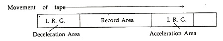
The process of reading or writing data to a tape involves bringing the tape quickly to the correct speed from rest and then carrying out the read/write operation. Once a record has been processed, the tape quickly decelerates and comes to the rest. This cycle is repeated for every record of data.
Naturally, no data can be recorded on the portion of the tape which is covered during acceleration and deceleration—these blank portions on the tape are variously called as Inter-Record Gap [IRG] or Inter-Block Gap [IBG] or End-of-Record Gap [ERG].
The tape moves at varying speed when travelling over the IRGs and at constant speed when moving over data areas. The speed of the tape, when at constant rate, varies from about 30 to 200 inches per second (ips). If the tape, moving at a speed of 112.5 ips [6 miles/hour] covers a distance of 3/8″ to accelerate and also to decelerate, then the IRG would be 3/8″ + 3/8″ = 3/4″.
The data is recorded on tape transversely, along the length of the tape in 7 or 9 channels by magnetizing bit positions on a vertical axis called a frame [byte or character], depending on the coding system used. The 7-channel recording is adopted for EBCDIC Code and 9- channel for BCD Code.
When we refer to an individual track or channel, we say recording as bits per inch, but when we refer to the tape as a whole, we say as characters [bytes] per inch. The density of the tape is expressed as bits per inch or bpi, the usual density being 800, 1600, or 6250 bpi. In modern high-density chromium tapes the density is as high as 38,000 bits per inch.
For error-checking, one outer channel in each tape is reserved for parity bits, which are determined from the number of odd or even bits in the other 6 or 8 channels, as the case may be. If odd-parity system is adopted, the total number of bits in a frame [bits in a vertical line] has to be odd, including the bit in the parity channel.
For example, if in a 7 channel tape, the number of is in the other 6 channels in a frame is 4, then a 1-bit is recorded in the parity channel to make the total 5, which is an odd number. If the total number of bits in the other 6 channels was 5, then the bit in the parity channel would be 0.
Similarly, an even-parity system can also be adopted. Thus, there is a parity bit for every frame in a tape where data is recorded. These are called vertical-parity check. Similarly, in each data space, at the end of each channel a horizontal-parity bit is determined, based on all the bits in that channel, depending on the odd or even parity system adopted.
Naturally, the last frame, at the end of data space, contains only parity bits, and the same outer channel contains the vertical-parity bit of horizontal-parity bits, which is called double-parity check.
During data reading, the value of the parity-bit is computed for each frame in the data-space and compared with that recorded in the parity-channel—in case they don’t tally, an error is indicated. While writing, the data written is immediately read after a fraction of a second and compared with what was recorded to detect errors if any.
The system of storing data is in the form of a data structure called “record”. If the number of bytes [characters] in a record is very small then the length of the tape required for recording each record would be very small as compared to the IRG, which is fixed by the speed of the tape-drive mechanism. Hence, there would be a large wastage of space on the tape, not containing any data.

To avoid this, a distinction is made between a Logical Record and a Physical Record, the former being how we view a record and the latter being how it is stored on the tape.
In practice, if the Logical Records are of fixed lengths, that is, each record provides for a fixed number of characters to be stored, then a number of Logical Records are combined to form a Physical Record or a Block of Data—the length of the physical-record divided by the length of the logical-record is called the Blocking Factor.
In other words, if 8 logical records are combined to form a physical record, the Blocking Factor is 8. Each block of data is always preceded and followed by an IRG, so, bigger the blocking- factor the lower the wastage of tape in IRGs.
In case of records of variable length, each logical record containing data of varying length, the process of blocking becomes a bit completed. In such cases, the variable record is broken into small fixed size records and then combined to form what is called spanned record format. During read/write operation the block is always processed and not the logical records; which is done by the program.

Apart from the data records stored in a file, there are two additional records of special types, when a file is stored in a magnetic tape. These two records are called Labels and are used at the beginning and end of the file as Header and Trailer labels, respectively.
The Header Label generally contains:
1. A specified field to denote that it is a header-label.
2. Name of the file and the date when created.
3. Purge date, that is, the date from which the file is not required.
Similarly, the Trailer-label contains:
1. A special field to denote that it is a trailer-label.
2. Total number of records in the file.
3. Name of the reel, if the file is too long requiring more than one spool of tape.
The program always checks these labels for necessary controls and the header-label ensures that the correct file is being processed.
ii. Magnetic Disk System:
Among all the secondary storage devices, so far magnetic disks hold a predominant position with its two broad classes, namely Hard Disks and Floppy Disks or in short Floppies or Diskettes, each with their own characteristics. Both are random or direct access storage devices, that is, any storage part in them can be accessed directly.
Both the type of disks have circular rotating surfaces coated with magnetic materials, but in case of hard disks the base material is rigid Aluminium plates to make them hard, whereas, floppy disks are made of flexible mylar plastic—hence the name given to each. A movable read/write is provided for each disk recording surface.

In case of floppies, there is only one disk enclosed in a white-felt lined paper jacket with opening for the read/write head to operate. So, the floppy has only two recording surfaces at the top and bottom sides, respectively called Side [head] 0 and Side 1.
In case of hard disks, a number of magnetically coated plates called platters are mounted centrally on a spindle, each surface having a movable read/write head except for the two outer surfaces at the top-most and bottom-most positions.
Hence, if three platters are used, the available surfaces are the four inner surfaces numbered as Sides [heads] 0, 1, 2, and 3 from the top side. The total assembly including the read/write heads is enclosed in a metal box which is hermetically sealed to make it air-tight. The hard-disk assembly is permanently fixed in the computer and being not movable, is also called a Fixed Disk.
When IBM first released a fixed disk with model number IBM 3030, indicating 30 Mega-Byte storage in each of the two sides of a platter, the hard disk acquired a nick-name of Winchester Disk—one of the famous Winchester rifle having the same model number. With large computers, hard disk- packs are available which can be removed as a whole.
The recording of data and other information on the magnetic surface is made by using the binary codes of a series of 0s and is in both the classes of the disks, which are done by the read/write heads as required. In case of floppies, the read/write head takes in average about 1/6 second to move to a specified location, which is 1/25 second in case of hard disks.
Hard disks rotate at a speed of 3600 rpm [rotation per minute] as against 300/360 rpm of floppies. The data transfer rate for hard disks is about 5 Mega-Bits/seconds, with that of floppies being 250 or 500 Kilo-Bits/second. The storage capacity of hard disks vary from 10 Megabyte [MB] to over 1000 MB, whereas that of floppies range from 320 KB to 1.44 MB, depending on the type.
To ensure proper storage and retrieval of data, each disk surface is divided into a number concentric circles called Tracks. Again, these individual tracks are divided into a fixed number of segments called Sectors.
The tracks are numbered as 0, 1, etc. starting with the outer edge and the sectors are numbered as 1, 2, etc. in each track. Under the ROM BIOS, to locate a specific sector, the head [side], track, and the sector numbers have to be specified.
Under MS DOS, each sector is numbered in sequence starting with Head 0, Track 0, and Sector 1 ending with the last sector in that track and then the Head is changed to 1 and the same sequence follows. Only when all the sectors in Track 0 are numbered, the read/write head moves to Track 1, and so on.
Hence, all the tracks of all the surfaces of a magnetic disk having the same track number are called a Cylinder. For example, in a hard disk, Track 0 of all the Heads from 0 to whatever surfaces there are, like 3 for 20 MB capacity, is collectively called Cylinder 0.

As far as floppy disks are concerned, the track density available is of two types, being 48 TPI [Tracks per inch] and 96 TPI, the higher one being used in high density floppies of 1.2 MB and 1.44 MB [micro-diskettes] capacities.
The term DSDD used in the label of a floppy means Double Sided Double Density, which is 48 TPI. A floppy is one in which both the sides can be treated as a single side diskette, by reversing the sides while putting it in the drive.
To access a data from a disk, the operating system starts the rotation of the disk and brings it quickly to a constant speed. The time required for this operation is called Rotational Time or Latency.
The time required to move the read/write head to the proper location is called Seek Time. Adding these two time elements we get what is called Access Time—which indicates how much time is required to store or retrieve a data from magnetic disks.
iii. Optical Disks:
The latest in the secondary storage devices is optical disks using laser beams, which are called CD ROM or Compact Disk Read Only Memory. As the name suggests, the contents of the these laser disks cannot be altered. These are very high capacity disks. For example, a 5 1/4″ CD ROM can store around 600 MB of data. The technology has been developed by Sony and Philips in 1970.
Data is recorded as tiny pits on a polished surface denoting 1, which are read by reflections produced when laser beams are focused on them. The disks are immune to dust and finger touches and there is no question of the read head crashing as it does not come in contact with the disk surface. Unfortunately, the costs are too high and it cannot be used for writing.

Another kind of optical disks are now becoming available which are called WORM or write-once-read-many times.