
Are you looking for an essay on the ‘Solar Cell’? Find paragraphs, long and short essays on the ‘Solar Cell’ especially written for school and college students.
Essay on the Solar Cell
Essay Contents:
- Essay on the Introduction to Solar Photovoltaic Cells
- Essay on Photovoltaic Effect on Solar Cell
- Essay on the Classification of Solar Cells
- Essay on the Conversion Efficiency and Power Output of a Solar Cell
- Essay on the Causes of Low Efficiency of a Solar Cell
Essay # 1. Introduction to Solar Photovoltaic Cells:
The “photovoltaic or solar cell” is a semiconductor device. The ‘photovoltaic effect’ was first observed in 1839 by Becquerel who found that, when light was directed on to one side of an electrochemical cell, a voltage was created. The development of selenium and cuprous oxide photovoltaic cells led to many applications, including photographic exposure meters. In the late 1950s, silicon solar cells were made with a conversion efficiency high enough for power generators.
Photovoltaic Materials:
The solar cells are made of various materials and with different structures in order to reduce the cost and optimize efficiency.
Various types of solar cell materials available in the market are:
i. The single crystal, polycrystalline and amorphous silicon, compound thin material and also semiconductor absorbing layer which gives highly efficient cells for specialised applications.
ii. Thin film solar cells are manufactured from CuInSe2, CdS, CdTe, Cu2S, InP.
iii. The amorphous silicon thin solar cells are less expensive while crystalline silicon cells are expensive and more popular. The amorphous silicon layer is used with both hydrogen and fluerine incorporated in the structure.
iv. Higher efficiency of photovoltaic generator can be achieved by combination of different bond gap materials in the tandem configurations.
Silicon Photovoltaic Cell (Single Crystal Solar Cell):
The main feature of a silicon photovoltaic cell is a thin wafer of high purity silicon crystal, doped with a minute quantity of boron (Fig. 4.30).

Phosphorous is diffused into the active surface of the slice by means of a high temperature process. The top electrical contact is made by a metallic grid, and the back metal contact covers the whole surface. The top surface usually has an anti-reflective coating (ARC).
Working Theory of Silicon Photovoltaic Cell:
i. The ‘phosphorous’ in the silicon causes an excess of conduction-band electrons, and the boron’ causes an excess of valence electron vacancies, or holes, which act like positive charges. At the “junction” between the two types of silicon, conduction electrons from the negative (n) region diffuse into the positive (p) region and combine with holes, thus cancelling their charges.
The opposite action also occurs, with holes from the p-region crossing into the n-region and combining electrons. The area around the junction is thus ‘depleted’ by disappearance of electrons and nearby holes. Layers of charged impurity atoms, positive in the n-region and negative in the p-region, are formed on either side of the junction, which sets up a ‘reverse’ electric field.
ii. When light falls on the active-surface, photons with energy exceeding a certain critical level known as band or energy gap (1.1 electron volt in the case of silicon) interact with the valence electrons and elevate them to the conduction band. This activity also leaves holes, so that the photons are said to generate ‘electron-hole pairs’.
These electron-hole pairs are produced throughout the thickness of the silicon in concentrations that depend on the intensity and spectral distribution of the light. The electrons move throughout the crystal, and the less mobile holes also move by valence-electron substitution from atom to atom.
Some recombine, neutralising their charges and their energy is converted into heat. Others reach the junction and are separated by the reverse field, at which point the electrons are accelerated towards the negative contact and the holes towards the positive. A potential difference is established across the cell, and this will drive a current through an external load.
Silicon voltaic cells require the use of very pure silicon. The best source of silicon is silica (silicon dioxide), which occurs abundantly in nature as quartz rock and sand. Quartz rocks are reduced in an arc-furnace with the help of carbon-based agents to produce ‘metallurgical grade’ silicon.
Polycrystalline Silicon Cells:
The cost of production of single crystal silicon cell is quite high compared to the polycrystalline silicon cell. Polysilicon can be obtained in thin ribbons drawn from molten silicon bath and cooled very slowly to obtain large size crystallites. Cells are made with care so that the grain boundaries cause no major interference with the flow of electrons and grains are larger in size than the thickness of the cell.
Following are the three designs in which the polycrystalline silicon solar cell can be fabricated:
1. p-n junction cells. In such a cell, a polycrystalline silicon film is deposited by chemical vapour deposition on substrates like glass, graphite, metallurgical grade silicon and metal.
2. Metal insulator semiconductor (MIS) cells. This type of cell can be developed by inserting a thin insulating layer of SO2 between the metal and the semiconductor.
3. Conducting oxide-insulator semiconductor cells.
Essay # 2. Photovoltaic Effect on Solar Cell:
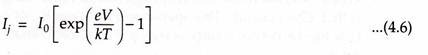
When a solar cell (p-n junction) is illuminated, electron-hole pairs are generated and the electric current I is obtained. I is the difference between the solar light generated current IL and the diode current Ij
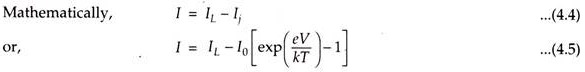
Where,
I0 = Saturation current,
e = Electron charge,
V = Voltage across the junction,
k = Boltzmann’s constant, and
T = Absolute temperature.
This phenomenon is known as the Photovoltaic effect.
Essay # 3. Classification of Solar Cells:
Solar cells can be classified on the basis of:
(i) Cell size;
(ii) Thickness of active material;
(iii) Type of junction structure;
(iv) Type of active material.
1. Cell Size:
The size of the silicon solar cells can be divided into four groups:
(i) Round single crystalline having 100 mm diameter;
(ii) Square single crystalline having area of 100 cm2,
(iii) 1000 mm x 1000 mm square multi-crystalline, and
(iv) 125 mm x 125 mm square multi-crystalline.
Larger size solar cells are used in terrestrial applications. Due to brittleness property of the silicon, area of Silicon solar cells is limited.
2. Thickness of Active Material:
Such solar cells are of two types:
(i) Bulk material cell, and
(ii) Thin film cell.
a. Bulk material single crystal and multi-crystalline cells are most successful for terrestrial applications.
b. Thin film cells are not commercially successful.
3. Type of Junction Structure:
These cells are classified as:
(i) p-n homojunction cell,
(ii) p-n hetrojunction cell,
(iii) p-n multijunction cell, and
(iv) Metal semiconductor Schottky junction.
4. Type of Active Material:
Such cells are classified as:
(i) Single crystal silicon cell,
(ii) Multi-crystalline silicon cell,
(iii) Amorphous silicon cell,
(iv) Gallium arsenide cell,
(v) Copper indium diselenide cell,
(vi) Cadmium telluride cell, and
(vii) Organic P-V cell.
Essay # 4. Conversion Efficiency and Power Output of a Solar Cell:
A solar cell uses a p-n junction its physical configuration.
The current and voltage relationship is given by:
Where,
l0 = Saturation current (also called dark current),
e = Electron charge,
V = Voltage across the junction, and
T = Absolute temperature.
Open circuit voltage Voc for the ideal cell is given by:
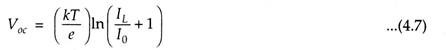
IL » I0, the 1 in the equation can be neglected.
Then open circuit voltage (Voc) becomes:
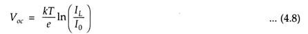
In practice the ‘open circuit voltage of the cell’ decreases with increasing temperature.
The voltage, current and power delivered by the solar cell are influenced by the following factors:
(i) Conditions of sunlight, intensity, wavelength and angle of incidence etc.;
(ii) Conditions of the junction, temperature, termination, etc.
(iii) External resistance(R).


The ratings of a solar cell are specified for particular reference conditions and with the help of V-l characteristics.
Fig. 4.28 represents a test condition. Fig. 4.29 gives V-l characteristics of a typical commercially available solar cell.
i. When external resistance R is high (mega-ohms range or infinity) the condition is called ‘Open-circuit’. The open-circuit voltage Voc of a solar cell is about 0.5 V.D.C. It. is the maximum voltage across a PV (photovoltaic) cell. Open-circuit current is zero.
ii. If R is reduced gradually and the readings of the terminal voltage V and load current I are taken, we get V-I, characteristics of the PV cell (Fig. 4.29).
iii. As R is reduced from high value to low value, the terminal voltage of the cell falls and current increases. A steep characteristic OK is obtained.
iv. At knee point ‘K’, the characteristic undergoes a smooth change and becomes flat for the portion Ks.
v. When the external resistance is completely shorted, the short-circuit current lsc is obtained. The terminal voltage for the short-circuit conditions is zero and maximum current delivered by the cell is lsc.
The maximum power (Pmax) that can be derived from the device is given by:
Pmax = Vmp Imp … (4.9)
where, Vmp and Imp are the voltage and current at maximum power point as shown in Fig. 4.29.
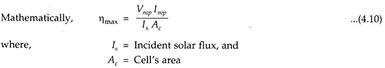
Maximum efficiency (ηmax) of a solar cell is defined as the ratio of maximum electric power output to incident solar radiation.
Fill Factor (FF):
The fill factor for a solar cell is defined as the ratio of two areas shown (Fig. 4.29). Mathematically,
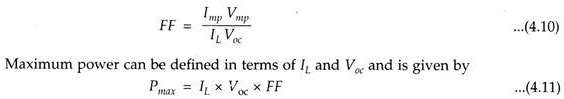
Solar cell designers strive to increase the FF values, to minimise internal losses. FF for a good silicon cell is about 0.8.
Voltage Factor:
The voltage factor eVoc/Eg is determined by the basic properties of the materials in the cell and is typically about 0.5 for a ‘silicon cell’ (Eg = Forbidden energy gap).
“Leakage” across the cell increases with temperature which reduces voltage and maximum power.
Essay # 5. Causes of Low Efficiency of a Solar Cell:
The efficiency of a photovoltaic cell is 15% only.
The major losses which lead to the low efficiency of the cell are:
1. As the temperature of the cell rises due to solar radiation, leakage across the cell increases. Consequently, power output, relative to solar energy input, decreases. For silicon, the output decreases by 0.5% per °C.
2. The excess energy of active photons given to the electrons beyond the required amount to cross the band gap cannot be recovered as useful electric power. It appears as heat, about 33 per cent, and is lost.
3. The electric current (generated) flows out of the top surface by a mesh of metal contacts provided to reduce series resistance losses. These contacts cover a definite area which reduces the active surface and proves an obstacle to incident solar radiation.
To achieve maximum efficiency the semiconductor with optimum band gap should be used.
Power output of solar panel, array and module:
Let, n = Number of solar cells in a module,
m = Number of modules in an array or a panel, and
Pc = Power per solar cell, watts
Then, Power per module, Pmod = nPc, watts …(4.12)
and, Power per array or panel Pp = m x nPc watts …(4.13)
Voltage across panel, Vp = Pp/Ip
Current delivered by the panel, Ip = √Pp/R…(4.14)