In this essay we will discuss about the concentrating and non-concentrating types of solar collectors that are used for collecting solar energy.
Essay # 1. Concentrating (or Focusing) Solar Collectors:
Concentrating collector is a device to collect solar energy with high intensity of solar radiation on the absorbing surface by the help of reflector or refractor. In these collectors, the area of collector is kept less than the aperture through which the radiation passes, to concentrate-the solar flux and has high concentration ratio.
Need of Orientation in Concentrating Collectors:
Such collectors generally use optical system in the form of reflectors or refractors. A concentrating collector is a special form of flat-plate collector modified by introducing a reflecting (or refracting) surface (concentrator) between the solar radiations and the absorber. These types of collectors can have radiation increase from low value of 1.52 to high values of the order of 10,000. In these collectors radiation falling on a relatively large area is focused on to a receiver (or absorber) of considerably smaller area. As a result of the energy concentration, fluids can be heated to temperatures of 500°C or more.
Orientation of sun from earth changes from time to time. So to harness maximum solar rays it is necessary to keep our collector facing to sun rays direction. This is the reason why orientation in concentrating collector is necessary. This is achieved by the use of “Tracking device”.
Types of Concentrating Collectors:
The different types of focusing/concentrating type collectors are:
i. Parabolic trough collector.
ii. Mirror strip collector.
iii. Fresnel lens collector.
iv. Flat-plate collector with adjustable mirrors.
v. Compound parabolic concentrator (CPC).
vi. Parabolic dish collector.
i. Parabolic Trough Collector:
Fig 3.4. shows the principle of the parabolic trough collector which is often used in focusing collectors. Solar radiation coming from the particular direction is collected over the area of reflecting surface and is concentrated at the focus of the parabola, if the reflector is in the form of a trough with parabolic cross-section, the solar radiation is focused along a line. Mostly cylindrical parabolic concentrators are used in which absorber is placed along focus axis [Fig. 3.5].


ii. Mirror Strip Collector:
Refer to Fig. 3.6. A mirror strip collector has a number of planes or slightly curved or concave mirror strips which are mounted on a base. These individual mirrors are placed at such angles that the reflected solar radiations fall on the same focal line where the pipe is placed. In this system, collector pipe is rotated so that the reflected rays on the absorber remain focused with respect to changes in sun’s elevation.

iii. Fresnel Lens Collector:
In this collector a Fresnel lens is used in which linear grooves are present on one side and flat surface on the other. The solar radiations which fall normal to the lens are refracted by the lens and are focused on the absorber (tube) as shown in Fig. 3.7. Both glass and plastic can be used as refracting materials for Fresnel lenses.

iv. Flat-Plate Collector with Adjustable Mirrors:
Fig. 3.8. shows a flat-plate collector with adjustable mirrors. It consists of a flat- plate collector facing south, with mirrors attached to its north and south edges. If the mirrors are set at the proper angle, they reflect solar radiation on to the absorber plate.
Thus, the latter receives reflected radiation in addition to that normally falling on it. In order to make the mirrors effective, the angles should be adjusted continuously as the sun’s altitude changes. Since the mirrors can provide only a relatively small increase in the solar radiation falling on the absorber, flat-plate collectors with mirrors are not widely used.

v. Compound Parabolic Concentrator (CPC):
Fig. 3.9 shows the compound parabolic concentrator. It was designed by Winston (and Baranov). It consists of two parabolic segments, oriented such that focus of one is located at the bottom end point of the other and vice versa. The receiver is a flat surface parallel to the aperture joining of two foci of the reflecting surfaces.
")
For thermal and economic reasons the fin and the tubular type of absorbers are preferable. It is claimed that Winston collectors are capable of competitive performance at high temperatures of about 300°C required for power generation, if they are used with selectively coated, vacuum enclosed receivers.
The maximum concentration ratio available with paraboloidal system is of the order of 10,000.
Advantages of Compound Parabolic Concentrator (CPC):
1. High concentration ratio.
2. No need of tracking.
3. Efficiency for accepting diffuse radiation is much larger than conventional concentrators.
vi. Paraboloidal Dish Collector:
Refer to Fig. 3.10. In this type of collector all the radiations from the sun are focussed at a point. This collector can generate temperature up to 300°C and contraction ratio from 10 to few thousands. Its diameter is of the range between 6 to 7 m and can be commercially manufactured.

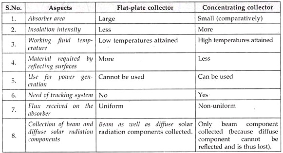
Comparison between Flat-Plate and Concentrating Collectors:
The comparison between flat-plate and concentrating collectors is given below:
Advantages of Concentrating Collectors:
1. High concentration ratio.
2. High fluid temperature can be achieved.
3. Less thermal heat losses.
4. System’s efficiency increases at high temperatures.
5. Inexpensive process.
Disadvantages of Concentrating Collectors:
1. Non-uniform flux on absorber.
2. Collect only beam radiation components because diffuse radiation components cannot be reflected, hence these are lost.
3. Need costly tracking device.
4. High initial cost.
5. Need maintenance to retain the quality of reflecting surface against dirt and oxidation.
Performance Analysis of a Concentrating Collector:
The useful heat output of a concentrating collector (Qc) is given by:
Qc = FR Aua [Ibc nopt – (Uoc/C) (tin – y] …(3.14)
where, FR = Heat removal factor of the collector,
Aua = Unshaded aperture area (m2),
Ibc = Intensity of beam solar radiation incident on the concentrator aperture (W/m2),
ηopt = Optical efficiency of the collector,
Uoc = Overall/total heat loss coefficient (W/m2oC),
C = Correction factor,
tin = The inlet temperature of the collector (°C), and
ta = Ambient temperature.
The “optical efficiency” of a concentrating collector (ηopt) is defined as the ratio of the solar radiation absorbed by the absorber to the beam solar radiation on the concentrator.
It is given by:
ηopt = ηopt 0° Copt = ργταa. Copt …(3.15)
where, ηopt0° = Optical efficiency of the collector at 0°-incident angle of beam radiation,
CopJ = Correction factor for deviation of incidence angle from 0°; p = Mirror reflectivity,
γ = Intefcept factor (It is defined as the ratio of radiation intercepted by absorber to the total radiation),
τ = Transmittivity of transparent cover of the absorber, and
αa = Absorptivity of the absorber.
The “efficiency” of a concentrating collector (ηc) is given by:
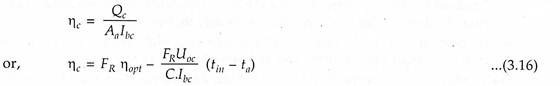
The outlet enthalpy (/;out) of heat transfer fluid in a concentrating collector with a phase change (vapourisation) of fluid is given by:
![]()
where, hin = Inlet enthalpy of heat transfer fluid (J/kg),
Qc = Useful heat output of collector (W), and
m = Mass flow rate of heat transfer fluid (kg/s).
Essay # 2. Non-Concentrating (or Flat-Plate Type) Solar Collector:
In such collectors, the area of a collector to grasp the solar radiation is equal to the absorber plate and has concentration ratio of 1.
1. An Absorber Plate:
It intercepts and absorbs solar radiation. This plate is usually metallic (copper, aluminium or steel), although plastics have been used in some low temperature applications. In most cases it is coated with a material to enhance the absorption of solar radiation. The coating may also be tailored to minimise the amount of infrared radiation emitted.
A heat transport fluid (usually air or water) is used to extract the energy collected and passes over, under or through passages which form an integral part of the plate.

2. Transparent Covers:
These are one or more sheets of solar radiation transmitting materials and are placed above the absorber plate. They allow solar energy to reach the absorber plate while reducing convection, conduction and re-radiation heat losses.
3. Insulation Beneath the Absorber Plate:
It minimises and protects the absorbing surface from heat losses.
4. Box-Like Structure:
It contains the above components and keeps them in position.
i. Various types of flat-plate collectors have been designed and studied. These include tube in plate, corrugated type, spiral wound type etc. Other criteria is single exposure, double exposure or exposure and reflector type. The collector utilizes sheets of any of the highly conducting material viz. copper, aluminium, or galvanized iron. The sheets are painted dead black for increasing the absorptivity.
The sheets are provided with one or more glass or plastic covers with air gap in between to reduce the heat transfer losses. The sides which are not exposed to solar radiation are well insulated. The whole assembly is fixed in airtight wooden box which is mounted on simple device to give the desired angle of inclination.
The dimensions of collectors should be such as to make their handling easy. The collector will absorb the sun energy (direct as well as diffused) and transfer it to the fluid (air, water or oil) flowing within the collector. Basically, a flat-plate collector is effective most of time, reliable for good many years and also inexpensive.
ii. Use of flat mirrors in the flat-plate collectors improves the output, permitting higher temperatures of operation. Side mirrors are used either at north and south edges or at east and west edges of the collector or a combination of both. The mirrors may be of reversible or non-reversible type.
Materials for Flat-Plate Collectors:
1. Absorber plate: Copper, Aluminium, Steel, Brass, Silver etc.
2. Insulation: Crown white wool, Glass wool, Expanded polystrene, foam etc.
3. Cover plate: Glass, Teflon, Tedlar, Marlex etc.
Selective Absorber Coatings/Surfaces:
In order to reduce thermal losses from the absorber plate of a solar heating panel, an efficient way is to use selective absorber coatings. An ideal selective coating is a perfect absorber of solar radiation as well as a perfect reflector of thermal radiation. A selective coating, thus, increases the temperature of an absorbing surface.
A “selective surface” has a high absorptance for shortwavfe radiation (less than 2.5 µm) and low emittance of longwave radiation (more than 2.5 µm).
A selective surface should possess the following characteristics:
(i) Its properties should not change with use;
(ii) It should be of reasonable cost;
(iii) It should be able to withstand the temperature levels associated with the absorber plate surface of a collector over extended period of time;
(iv) It should be able to withstand atmospheric corrosion and oxidation.
Some selective coatings are:
(i) Black chrome;
(ii) Black nickel;
(iii) Black copper;
(iv) Silver foil;
(v) Enersorb (nonselective);
(vi) Nextel (non-selective).
Advantages of Flat-Plate Collectors:
1. Both beam and diffuse solar radiations are used.
2. Require little maintenance.
3. The orientation of the sun is not required (i.e. no tracking device needed)
4. Mechanically simpler than the focusing collectors.
Disadvantages of Flat-Plate Collectors:
1. Low temperature is achieved.
2. Heavy in weight.
3. Large heat losses by conduction due to large area.
Applications of Flat-Plate Collectors:
1. Used in solar water heating.
2. Used in solar heating and cooling.
3. Used in low temperature power generation.
Performance Analysis of Flat-Plate Collector:
Analysis:
Consider an object exposed to sun radiations of intensity I, per unit area at the surface of the body. These radiations will partly be absorbed by the body, while the remaining will be partly transmitted and rest reflected. If we take the incident radiations equal to unity, then the absorbed, reflected, and transmitted parts of energy will add up to unity. These parts are called absorption coefficient, reflection coefficient and transmission coefficient and represented by the symbols α, p and τ respectively.
Using the above symbols we can write,
α + p + τ = 1 …(3.1)
The absorbed part of the solar radiations, which is equal to a, is responsible for increasing the temperature of the body. However, the body also loses energy by conduction, convection and radiation. The equilibrium temperature of the body will be that at which the heat loses from the body are equal to the absorbed radiations.
For analysis purposes, if we represent the body by a flat a plate and assume that the convection and conduction losses are negligible to begin with, then at equilibrium temperature the absorbed solar radiations should be equal to the radiation losses from the flat plate. The radiation losses are equal to εσT4, where s and T are the emission coefficient and absolute temperature respectively of a flat plate and a is the Boltzman’s constant.
Therefore, at equilibrium,
αI = εσtT4 …(3.2)
or, αI/ε = σT4 …(3.3)
From equation (3.3), it is evident that comparatively higher equilibrium temperature will be obtained where the quantity α/ε i.e., the ratio of absorption coefficient to emission coefficient of the flat plate is more. However, this has been demonstrated by an equation obtained under idealised condition. In the realistic conditions too, its nature will remain the same, but it will get modified by other influencing factors.
The collectors for which ratio is equal to unity are called ‘Neutral collectors’ and those for which the ratio is greater than unity are called ‘Selective collectors’.
The amount of energy collected, however, does not depend on α/ε ratio. It primarily depends on higher value of a. So to obtain higher energy collection, one should use such flat plate where absorption coefficient is as high as possible.
A flat plate painted black is placed on a well-insulated base. If it is exposed to solar radiations where I = 800 W/m2, a typical summer value for a tropical region, we obtain from equation (3.3) the equilibrium temperature as 70°C. In spite of the simplifications here, it is a fair estimate of the temperature reached by a black plate left for a time in the tropical sun.
This method can be refined by including the convection losses and the energy gain as a result of absorption of diffused radiations by the flat plate.
If I’ is the intensity of the diffused radiations and a’ the absorption coefficient, then equation (3.2) becomes,
αl + α’I’ = hc(T – Ta) + εσT4 …(3.4)
This is valid, where the base is insulated, hence conduction losses are neglected. Here Ta is the atmospheric temperature and hc is the convection heat transfer coefficient.
Transmissivity-Absorptivity Product (τ.α):
The effective part radiation absorbed is given by:

The value of pd for an incident angle of 60° is about 0.16, 0.24 and 0.2 for one, two and three glass covers respectively.
Performance:
The “performance of a flat-plate collector” is described by an energy balance that indicates the distribution of incident solar energy into useful energy gain and various losses.
Under Steady Conditions:
Useful heat delivered by a solar collector
= Energy absorbed in the metal surface — Heat losses from the surface directly and indirectly to the surroundings.
Useful heat output of a flat-plate collector is given by:
Qc = Acs [Ics (τα)Uoc(tfi –ta)] watts …(3.6)
Qc = Useful heat output of flat-plate collector (W),
Acs = Collector surface area (m2),
Ics – Intensity of solar radiation incident on the collector surface (W/m2),
τ = Transmission coefficient {i.e., fraction of incoming solar radiation that reaches the absorbing surface)
α = Absorption coefficient (i.e. fraction of the solar radiation reaching the surface that is absorbed)
(τα)e = Effective product of transmittivity of the transparent cover and absorptivity of the absorber,
Uoc = Overall total heat loss coefficient of the collector (W/m°C),
tfi = collector fluid inlet temperature (°C), and
ta = Ambient air temperature (°C).
Introducing heat “removal factor FR” in (Eqn. (3.6), we get,
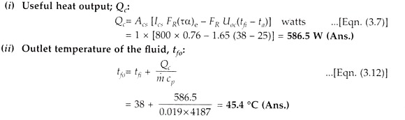
Qc = Acs [Ics FR (τα)e – FR Uoc (tfi – tα)] watts …(3.7)
The “efficiency of a solar collector (ηc)” is defined as the ratio of the useful heat output of the collector to the solar energy flux incident on the collector.
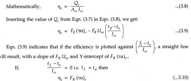
This is the effective optical efficiency.
The energy balance equation on the whole collector can be written as:
Acs[IcsFR (p.α)b + IcsFR(τ.a)d] = Qu + Ql+ Qs …(3.11)
where, Qu = Rate of useful heat transfer to a working fluid in the solar heat exchanger,
Ql = Rate of energy losses from the collector to the surroundings by re-radiation, convection and by conduction through supports for the absorber plate and so on. The losses due to reflection from the covers are included in the (τ.α) terms, and
Qs = Rate of energy storage in the collector.
Suffices, b and d stand for beam and diffuse radiations respectively.
The outlet temperature of collector heat transfer fluid, fy0 (0°C)
The outlet temperature of collector heat transfer fluid tjn is given by:
![]()
where, ffi = Collector fluid inlet temperature (°C),
Qc = Useful heat output of collector (W),
in = Mass flow rate of collector fluid (kg/s), and
cp = Specific heat of collector rluid (J/kg K).
The stagnant temperature (fs) of the collector is defined as the temperature of the absorber which is achieved when there is no flow of heat transfer fluid in the collector and therefore, its useful heat output and efficiency both are equal to zero.
Hence, for Eqn. 3.7, we get:
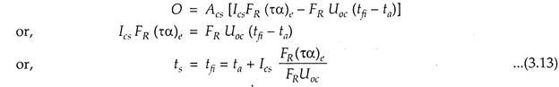
It is evident from Eqn. (3.13) that ts will be high, if Ics and (ta),, are high and FR Uoc is
Factors Affecting the Performance of a Flat-Plate Collector:
The following factors affect the performance of a flat-plate collector:
1. Incident solar radiation
2. Number of cover plates.
3. Spacing between absorber plate and glass cover.
4. Tilt of the collector.
5. Selective surface.
6. Fluid inlet temperature.
7. Dust on cover plate.
1. Incident Solar Radiation:
The collector’s efficiency is directly related to solar radiation falling on it and increases with rise in temperature.
2. Number of Cover Plates:
The increase in number of cover plates reduces the internal connective heat losses but also prevents the transmission of radiation inside the collector.
3. Spacing between Absorber Plate and Glass Cover:
The more the space between the absorber and the cover plate, the less is the internal heat loss.
4. Tilt of the Collector:
In order to achieve better performance, flat-plate collector should be tilted at an angle of latitude of the location.
The collector is placed with south facing at northern hemisphere to receive maximum radiation throughout the day.
5. Selective Surface:
The selective surface should be able to withstand high temperature, should not oxidise and should be corrosion resistant.
6. Fluid Inlet Temperature:
With the increase in the inlet temperature of the fluid, there is an increase in operating temperature of the collector and this leads to decrease in efficiency.
7. Dust on Cover Plate:
The collector’s efficiency decreases as dust particles increase on the cover plate. Thus, frequent cleaning is required to get the maximum efficiency of the collector.
Example:
The following data relate to an evacuated tube collector:
The intensity of solar radiation on the collector’s surface = 800 W/m2;
The inlet temperature of the fluid = 38 °C;
The ambient air temperature = 25 °C
Effective optical efficiency = 0.76
Effective heat loss coefficient = 1.65 W/m2K
Mass flow rate of water = 0-019 kg/s/m
Specific heat of water at constant pressure = 4287 J/kg K
Calculate the following:
(i) Useful heat output, per m2 of the surface area.
(ii) Outlet temperature of the fluid.
(iii) Stagnation temperature.
Solution:
Given- Ics = 800 W/m2; Acs = 1m2; tfi = 38 °C; ta = 25 °C; FR (τα)e = 0.76; FR Uoc = 1.65 W/m2K; m = 0.019 kg/s/m2, cp = 4187 J/kg K.