Are you looking for an essay on the ‘Classification of Tidal Power Plants’? Find paragraphs, long and short essays on the ‘Classification of Tidal Power Plants’ especially written for school and college students.
Essay # 1. Single-Basin Tidal Plants:
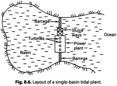
Fig. 8.6 shows the layout of a single-basin tidal plant.
i. A barrage (Dyke, dam) separate, the basin from the sea.
ii. The sluice way is opened during high tide to fill the basin.
iii. The turbine-generator units are mounted within the ducts inside the barrage.
iv. Power house is built on the barrage.
a. A single-basin tidal plant cannot generate power continuously.
b. In these plants, pumped storage capacity may be incorporated to fill water to a higher level and empty the basin to lower level. A pumped storage plant is useful when the load it supplies fluctuates considerably.
(i) Single-Basin Single-Effect Plant:
Refer to Fig. 8.4. Such a plant generates power only with one-way flow of water through the turbines, i.e., during low tide.
i. The basin is filled during the ‘high-tide’ by opening the gates in the barrage. The water level in the basin reaches the crest level of the tide. The energy is stored in the form of tidal range. Tidal range gives the head of water during the ‘low tide’.
ii. Initially, during the low tide, the level in the basin is R is zero. Water is released during the generating mode through the turbines, spillways located within the barrage, into the sea.
iii. The turbines are started only when the head reaches (R) i.e., water in the basin is at high tide level and water in the sea is at low tide level. The turbines are designed for single way operation. Only fixed blade turbines are necessary.
Power generation is intermittent and mostly during off-peak load periods on daily load curves.
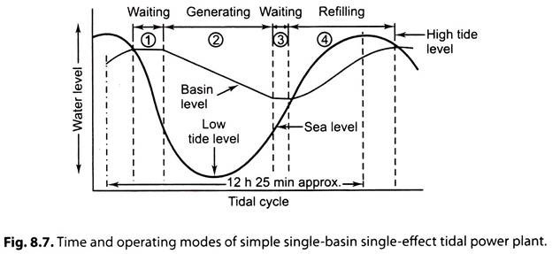
Fig. 8.7. Indicates the flow intervals in a simple single-basin and single-effect plant.
a. First Waiting Mode:
i. It begins with the falling water level and lasts for 1.5 hours (approx.) to allow the ocean water level to reduce and head H to increase.
ii. The basin level remains at top during the waiting mode.
b. Generating Mode:
i. This mode begins, when the ocean level reduces to required mark and the head H reaches required value.
Head = Basin water level-sea water level
ii. The turbine-gates are opened, and the pool water flows through the turbines (during this mode).
iii. This mode continues during ’emptying’ of the basin and last for 4.5 hours (approx.)
3. Second waiting mode: The generating mode is followed by another waiting mode, during the rising tide.
4. Refilling mode: Its duration is 4.0 hours (approx.) during the rising tide.
(ii) Single-Basin Double-Effect Plant:
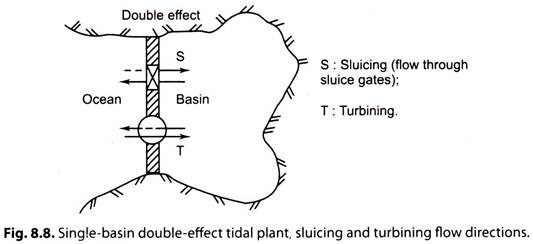
Refer to Figs. 8.5 and 8.8. This is a two-way scheme, Ebb and flood operation. Reversible turbines are installed and power is generated during ‘filling’ and ’emptying’ of the basin.
i. The basinfills in during rising tide (flooding). The water flows from the sea to the basin and drives the reversible turbines.
ii. The basin is emptied during lowering-tide (ebbing).
Water flows from the basin into the sea and drives the reversible turbines.
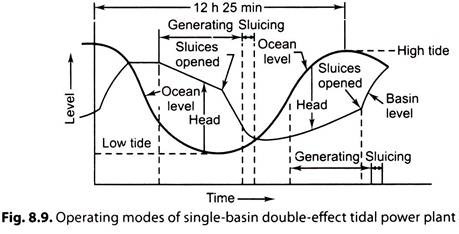
Fig. 8.9 shows the operating modes of single-basin double-effect tidal power plant.
The operating modes during 12 h 25 min half-tidal cycle are:
1. Generating mode during emptying.
2. Sluicing—letting out water through sluice during low net heads.
3. Generating period during filling—sluices are closed, water is let out from the basin through the turbines.
4. Second sluicing period.
Energy conversion in half tidal period of 12h 25 min is twice that of a single-basin single-effect plant.
In a single-basin, double-effect, ‘pump turbine plant’ in addition, the turbines are used as pumps to increase or reduce the water level of the basin/reservoir some energy is spent to drive the pumps.
Although the double-cycle system has only short duration interruptions in turbine operation, yet a continuous generation of power is still not possible. Furthermore the periods of power generation coincide only occasionally with periods of peak demand. These problems are overcome to some extent in the double-basin scheme.
Essay # 2. Double-Basin Tidal Plants:
A ‘double-basin scheme’ can produce continuous power output. The drawback is that the civil works become more extensive.
Several tidal energy conversion projects under planning are of double-basin type.
These plants may be of the following two types:
(i) Double-basin, linked-basin plant.
(ii) Double-basin, paired-basin plant.
(i) Double-Basin, Linked-Basin Scheme:
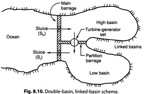
Refer to Fig. 8.10. In this scheme a single larger basin is divided into two basins called high basin and low basin. These basins are separated by means of a partition barrage.
The Main Barrage is Built between the Sea and the Two Basins:
i. High basin gets periodically filled during every high tide from ocean water through sluice Sh.
ii. Low basin gets periodically emptied by flow to ocean through sluice Sl during low
iii. Turbine-generator set(s) are installed in the partition barrage. Water flows from high basin to low basin is through turbines. This flow is controlled such that continuous power is obtained from the plant, without waiting for tidal sequence. High basin acts as an energy reservoir.
iv. The capacities of the two basins should be large enough in relation to the water flow through the turbines so that fluctuations in head of water (the difference in levels between high basin and low basin) during power generation is minimised.
(ii) Double-Basin, Paired-Basin Scheme:
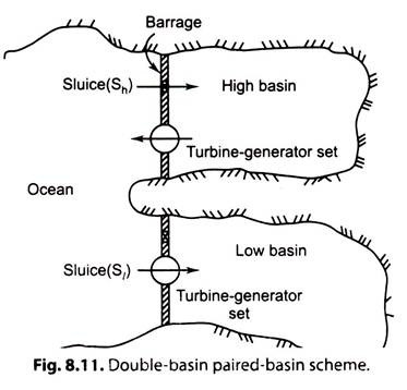
Refer to Fig. 8.11. In a double-basin, paired-basin scheme two barrages are built between the ocean and each basin. In such a scheme, supplementary pair-basins can be added and the total scheme becomes a ‘multiple basin scheme’ with a few paired basins.
Fig. 8.11. shows a schematic diagram of a double-basin, paired-basin scheme. In this scheme, power is generated during low tide and high tide.
i. During high tide, high basin is filled by sluice Sh.
ii. During low tide, high basin discharges via turbine (s).
iii. During high tide, low basin is filled via turbine (s).
iv. During low tide, low basin is sluiced via Sl.
Limitations:
1. Although this scheme leads to continuous output, yet its power supply remains irregular and there is no solution for equalising the great difference in output between the spring and the neap tide operation.
2. It is difficult to find two tidal sites within reasonable distance of each other having the requisite difference is time of high water.
