In this essay we will discuss about the classification of wave machines that are basically employed for energy conversion from the wave.
Essay on Wave Machines
Essay Contents:
- Essay on Float Wave-Power Machine
- Essay on High-Level Reservoir Wave Machine
- Essay on Dolphin-Type Wave-Power Machine (Generator)
- Essay on Hydraulic Accumulator Wave Machine
- Essay on Nodding / Oscillating Ducks Wave Machine
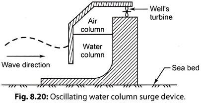
- Essay on Oscillating Water Column Surge Device
Essay # 1. Float Wave-Power Machine:
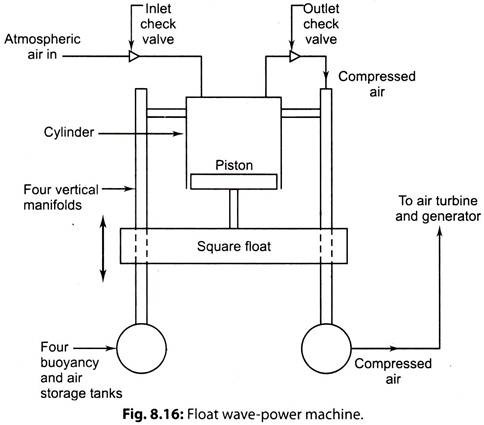
Wave motion is primarily ‘horizontal’, but the motion of the water is primarily ‘vertical’. Mechanical power is obtained by floats making use of the motion of water. The concept visualises a large float that is driven up and down by the water within relatively stationary guides. This reciprocating motion is converted into mechanical and then electrical power is generated.
Fig. 8.16. shows Martin’s float wave-power machine.
Construction of Float Wave-Power Machine:
It consists of a ‘square float’ which moves up and down.
‘Four vertical manifolds’ that are part of a platform guide the floats. A ‘piston’ attached to the float compresses air in a ‘cylinder’ which is stationary with the platform. The piston- cylinder arrangement acts as a reciprocating air compressor.
Working of Float Wave-Power Machine:
i. The downward motion of the piston draws air into cylinder via inlet check valve.
ii. The upward motion compressor the air and send it through an outlet check valve to the four underwater floatation tanks via the four manifolds. These tanks serve the dual purpose of buoyancy and air storage tanks and the four manifolds serve the purpose of float guides and discharge air pipes.
iii. The compressed air in the buoyancy – storage tanks is then used to driver an air turbine which in term runs an electric generator, and the electricity is transmitted to the shore via underwater cable.
Limitations of Float Wave-Power Machine:
1. Waves are not perfectly sinusoidal.
2. Linear arrays of several kilometres are required to produce 100 MW.
3. Aspiration of water into intake systems and submersion by large waves.
4. Water entering turbine.
5. Design to withstand storms.
6. Transmission of power to shore.
7. Marine growth.
Essay # 2. High-Level Reservoir Wave Machine:
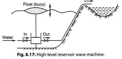
Fig. 8.17 shows a high-level reservoir machine. In this system an hydraulic pump is operated by the motion of buoy to raise water to onshore reservoir. The water in the reservoir is made to flow through a turbo-generator to generate electricity, and then back to sea level.
Essay # 3. Dolphin-Type Wave-Power Machine (Generator):
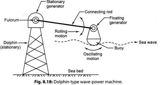
This wave-power machine was designed by a research laboratory in Japan. It consists of the following components (Fig. 8.18):
1. A dolphin;
2. Afloat;
3. A connecting rod;
4. Two electrical generators.
i. A “stationary generator”, installed on the top of the structure, collects wave energy from the “connecting rod” with rolling motion. This generator has a gear arrangement which rotates the rotor to generate electric power.
ii. The “buoy” which is at the other end of the connecting rod float has two motions, namely rolling motion and oscillatory motion. The “floating generator” collects wave energy from the buoy through a gear arrangement and generates electric power continuously.
The power density (P/B) is given by the relation:
P/B = 1740a2 T W/m
where, P = Power, W
B = Wave width, m
a = Amptitude of the wave, m, and
T = Wave period, s.
The capacity of one dolphin type wave energy generator, normally, is 100 kW.
Example:
Calculate the installed capacity of a plant consisting of an array of dolphin type wave energy generators installed along a width 450 m. The mean amplitude of the wave is 2.2 m with a period of 9 s.
Solution:
Given:
B = 450 m; a = 2.2 m; T = 9 s
Using the relation: P/B = 1740 a2T, we get: …[Eqn. (8.21)]
P = Bx 1740 a2 T = 450 x 1740 x (2.2)2 x 9 x 10-6 MW
= 34.1 MW (Ans.)
Essay # 4. Hydraulic Accumulator Wave Machine:
In this type of machine low-pressure water (at wave crust) is pressurized and stored in a ‘high-pressure accumulator’, from which it flows through a water-turbine electric generator.
i. A composite piston is composed of a large-diameter main system and a. small- diameter piston at its centre. As the wave water enters through the opening, the main piston moves up and down. A closed water loop exists above the small piston. During the upstroke, the pressure on the main piston is magnified.
ii. The high-pressure water then moves through a one-way valve to a hydraulic accumulator at the top of the generator.
iii. High-pressure water flows through a hydraulic turbine that drives an electrical generator and is then discharged to a storage chamber below the turbine.
Essay # 5. Nodding / Oscillating Ducks Wave Machine:
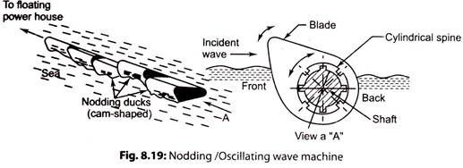
Refer to Fig. 8.19. This wave machine was designed by Stephen Salter at Edinburgh university in Scotland.
It consists of several duck-shaped devices (each 25 m long), installed in a linear width- wise array along a line which is perpendicular to the direction of wave.
i. When the forward moving wave front strikes the head on the face of the ducks, wave energy is passed on and ducks start to oscillate.
ii. The ratchet and wheel mechanism conduct the oscillating motion of the ducks to the axial shaft. The wave energy is converted to mechanical energy (by the relative motion of the ducks). The shaft drives linkages, gears and the rotor of electric generator (the overall length of the cylindrical spine varies between 100 to 500 m).
Essay # 6. Oscillating Water Column Surge Device:
Refer to Fig. 8.20. When a moving wave is constricted, a surge is produced raising its amplitude. Such a device is known as tapered channel device (TAPCHAN). It comprises gradually narrowing channel with heights typically 3 to 5 m above sea level.
The waves enter from the wide end of the channel and then propagate towards narrower region. The wave heights get amplified until the crests spills over the walls to a reservoir, which provides a stable water supply to a low head turbine.
The arrangement can be implemented successfully at low tide sites only:
An off shore boating wave power vessel having TAPCHAN plant on a steel platform is suggested to make the system insensitive to tidal range.
