Are you looking for an essay on the ‘Types of Microscope’? Find paragraphs, long and short essays on ‘Types of Microscope’ especially written for school and college students.
1. Essay on Light Microscope:
Dutch spectacle makers, Zaccharias Janssen and his son Hans (1590), while experimenting with several lenses in a tube, discovered that nearby objects appeared greatly enlarged. That was the forerunner of the compound microscope and of the telescope. In 1609, Galileo, father of modern physics and astronomy, heard of these early experiments, worked out the principles of lenses, and made a much better instrument with a focusing device.
Anton van Leeuwenhoek, the father of microscopy, started his career as an apprentice in a dry goods store where magnifying glasses were used to count the threads in cloth. He made tiny lenses of great curvature which gave magnifications up to 270 diameters, the finest known at that time by grinding and polishing. He was the first to see and describe bacteria, yeast plants, the teeming life in a drop of water, and the circulation of blood corpuscles in capillaries. During a long life he used his lenses to make pioneer studies on an extraordinary variety of things, both living and non-living, and reported his findings in over a hundred letters to the Royal Society of England and the French Academy.
Robert Hooke, re-confirmed Anton van Leeuwenhoek’s discoveries of the existence of tiny living organisms in a drop of water. Hooke made a copy of Leeuwenhoek’s light microscope and then improved upon his design.
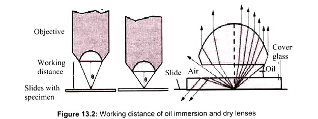
The light microscope, so called because it employs visible light to detect small objects, is probably the most well-known and well-used research tool in biology. Microscope must gather light from a tiny area of a thin, well-illuminated specimen that is close-by. So the lens of a microscope is small and spherical, which means that it has a much shorter focal length on either side.
It brings the image of the object into focus at a short distance within the microscope’s tube. The image is then magnified by a second lens, called an ocular lens or eyepiece, as it is brought to your eye. Microscope has a light source and a condenser. The condenser is a lens system that focuses the light from the source on to a tiny, bright spot of the specimen, which is the same area that the objective lens examines.
i. Compound Light Microscope:
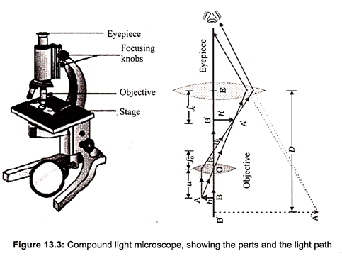
The compound light microscope uses two sets of lenses to magnify the object. Illumination is provided by a light source on the base of the microscope (Fig. 13.3). The magnification typically ranges from approximately 40 X to 1,000 X. They can be used with objects that range in size from about 100 nm to 2 mm.
ii. Parts of the Light Microscope:
The stage is a platform that holds the slide containing the specimen to be viewed. A mechanical stage has a mechanism for moving the slide. A light microscope must have a light source. This is usually a light bulb located beneath the stage. An adjustable diaphragm located beneath the stage is used to regulate the amount of light that passes through. A condenser contains two sets of lenses that concentrate light. It is located directly underneath the stage. Light from the light source passes through the diaphragm and condenser before continuing up through the specimen to be viewed. The body tube contains an ocular lens (eyepiece) and a nosepiece with several objective lenses. Each objective lens is used for a different magnification and is moved into place by rotating the nosepiece. The image is brought into focus by adjusting the coarse and fine focus knobs.
iii. Types of Light Microscopy:
a. Bright Field Microscopy:
In conventional bright field microscope, light from a source is aimed towards a lens beneath the stage called the condenser that passes through the specimen, followed by an objective lens and finally reaches to the eye through a second magnifying lens, referred to as ocular or eyepiece. The bright field condenser usually contains an aperture diaphragm, a device that controls the diameter of the light beam coming up through the condenser, so that when the diaphragm is stopped down (nearly closed) the light comes straight up through the center of the condenser lens and contrast is high. When the diaphragm is wide open the image tend to be brighter, while contrast turns to be low.
Basic dyes, used to stain, have a positively charged chromophore (color-bearing ion) that is attracted to the slightly negatively charged cells. The specimen will appear as a colored shape in a bright background. Bright field microscopy is best suited to viewing stained or naturally pigmented specimens such as stained prepared slides of tissue sections or living photosynthetic organisms. It is useless for living specimens of bacteria, and inferior for non- photosynthetic protists or metazoans, or unstained cell suspensions or tissue sections.
b. Dark Field Microscopy:
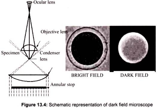
Dark field microscopy is a method which also creates contrast between the object and the surrounding field. As the name implies, the background is dark and the object is bright. An annular stop is also used for dark field. Only light coming from the outside of the beam passes through the object and it cannot be seen directly. The following diagram shows the setup of the dark field light path (Fig. 13.4).
To view a specimen in dark field, an opaque disc is placed underneath the condenser lens, so that only light that is scattered by objects on the slide can reach the eye. Instead of coming up through the specimen, the light is reflected by particles on the slide. Everything is visible regardless of color, usually bright white against a dark background. Pigmented objects are often seen in “false colors,” that is, the reflected light is of a color different than the color of the object. Better resolution can be obtained using dark field as opposed to bright field viewing.
c. Phase Contrast Microscopy:
Phase contrast microscopy, first described in 1934 by Dutch physicist Frits Zernike, is a contrast-enhancing optical technique that can be utilized to produce high-contrast images of transparent specimens, such as living cells (usually in culture), microorganisms, thin tissue slices, and subcellular particles (including nuclei and other organelles).
Most of the detail of living cells is undetectable in bright field microscopy because there is too little contrast between structures with similar transparency and there is insufficient natural pigmentation. However, the various organelles show wide variation in refractive index, that is, the tendency of the materials to bend light, providing an opportunity to distinguish them. Highly refractive structures bend light to a much greater angle than do structures of low refractive index.
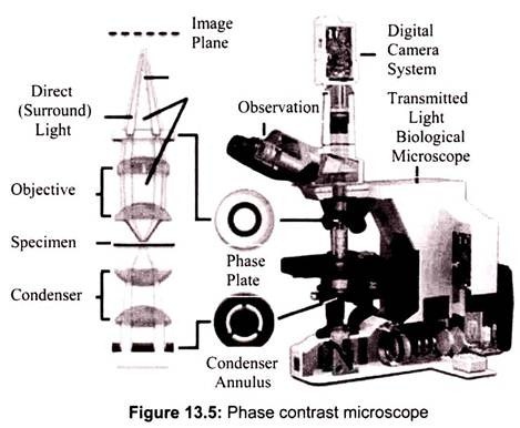
The same properties that cause the light to bend also delay the passage of light by a quarter of a wavelength or so. In a light microscope in bright field mode, light from highly refractive structures bends farther away from the center of the lens than light from less refractive structures and arrives about a quarter of a wavelength out of phase.
Light from most objects passes through the center of the lens as well as to the periphery. Now, if the light from an object to the edges of the objective lens is retarded a half wavelength and the light to the center is not retarded at all, then the light rays are out of phase by a half wavelength. They cancel each other when the objective Jens brings the image into focus. A reduction in brightness of the object is observed. The degree of reduction in brightness depends on the refractive index of the object.
Phase contrast is preferable to bright field microscopy when high magnifications (400x, 1000x) are needed and the specimen is colorless or the details so fine that color does not show up well. Cilia and flagella, for example, are nearly invisible in bright field but show up in sharp contrast in phase contrast. Amoebae look like vague outlines in bright field, but show a great deal of detail in phase. Most living microscopic organisms are much more obvious in phase contrast (Fig. 13.5).
d. The Fluorescence Microscope:
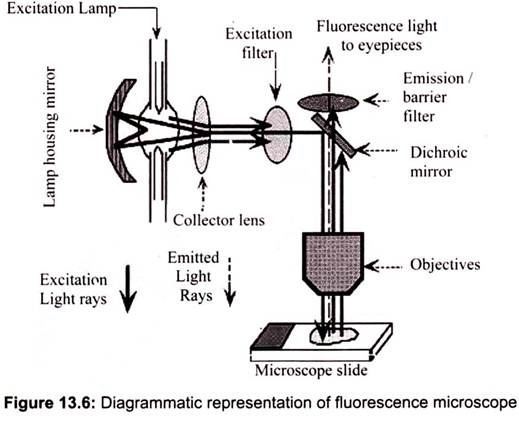
Fluorescence microscopy works on the principle of fluorescence. Energy is absorbed by the atom which becomes excited. The electron jumps to a higher energy level. Soon, the electron drops back to the ground state, emitting a photon (or a packet of light) – the atom is fluorescing. The technique is used to study specimens, which can be made to fluoresce. The fluorescence microscope is based on the phenomenon that certain material emits energy detectable as visible light when irradiated with the light of a specific wavelength. The sample can either be fluorescing in its natural form like chlorophyll and some minerals, or treated with fluorescing chemicals (Fig. 13.6).
The basic task of the fluorescence microscope is to let excitation light radiate the specimen and then sort out the much weaker emitted light to make up the image. First, the microscope has a filter that only lets through radiation with the desired wavelength that matches fluorescing material. The radiation collides with the atoms in the specimen and electrons are excited to a higher energy level. When they relax to a lower level, they emit light. To become visible, the emitted light is separated from the much brighter excitation light in a second filter. Here, the fact that the emitted light is of lower energy and has a longer wavelength is used. The fluorescing areas can be observed in the microscope and shine out against a dark background with high contrast.
2. Essay on Electron Microscope:
Electron Microscopes were developed due to the limitations of light microscopes which are limited to 500x or 1000x magnification and a resolution of 0.2 micrometers. Simple light microscopy cannot be used to distinguish objects that are smaller than half the wavelength of light. White light has an average wavelength of 0.55 micrometers, half of which is 0.275 micrometers. Any two lines that are closer together than 0.275 micrometers will be seen as a single line, and any object with a diameter smaller than 0.275 micrometers will be invisible or, at best, show up as a blur. By using blue/violet light (400 nm) by decreasing the wave- length. It can approximately double the resolution that can be obtained using red (600 nm) or white (mean 500 nm) light, but a doubling of the resolution is hardly a great improvement.
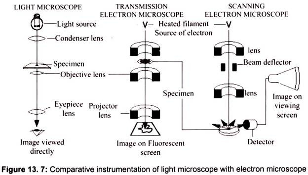
Max Knoll and Ernst Ruska in 1931 introduced the electron microscope. Ernst Ruska was awarded the Nobel Prize for Physics in 1986 for his invention. A stream of electrons is formed (by the electron source) and accelerated toward the specimen using a positive electrical potential. This stream is confined and focused using metal apertures and magnetic lenses (condenser) into a thin, focused, monochromatic beam. This beam is focused onto the sample using a magnetic lens. Interactions occur inside the irradiated sample, affecting the electron beam. These interactions and effects are detected and transformed into an image, which contains information such as structure and composition (Fig. 13.7).
i. Components of Electron Microscope:
The various components of the microscope can be categorized as:
(1) The electron column,
(2) The specimen chamber,
(3) The vacuum pumping system and
(4) The electron control and imaging system.
a. The Electron Gun:
The electron gun produces a narrowly divergent beam of electrons directed down the center- line of the column. The electrons are produced by thermionic emission at filament and are attracted to the anode. The anode is maintained at a positive voltage relative to the filament, ranging from 5 to 30 kV in scanning electron microscopes. This voltage, controlled by the operator, is generally held at 20 kV, but variations can be useful for structure and X-ray analysis.
b. Lenses:
Electron microscopes have magnetic lenses that are similar to simple solenoids. A coil of copper wire produces a magnetic field that is shaped by the surrounding iron fixture into an optimum geometry. As an electron moves through the magnetic field, it experiences a radial force inward, which is proportional to the Lorenz force; v x B, where v is the electron velocity and B is the magnetic flux density. The lensing action is similar to that of an optical lens, in which a ray parallel to the axis of the lens is bent to the lens axis at the focal length f, of the lens. In an optical lens, the focal length is fixed by the curvature of the lens surfaces and cannot be changed.
In the electromagnetic lens, the focal length depends on two factors:
a. The gun voltage (which determines the electron velocity v and
b. The amount of current through the coil (which determines the flux density, B).
Therefore, the operator controls the focal lengths of the lenses by adjusting the currents supplied to them.
c. Scan Coils and Raster Formation:
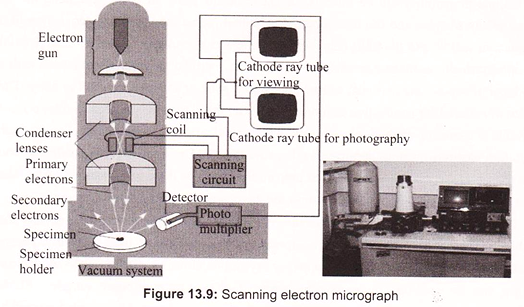
The scanning electron microscope causes the electron beam to scan the sample surface. The two sets of scan coils (one for raster, one for deflection) are located in the bore of the objective lens cage and perform the scanning function. These coils cause the beam to scan over a square area on the sample surface. A double-deflection system is used, with the beam deflected by the Lorentz force produced from the magnetic fields of coil pairs. The scan generator controls the frame and line times as well as the raster size. The double-deflection system allows the electron beam to pass through the principal plane of the objective lens very close to on-axis, which reduces lens aberration.
d. Detectors and Image Formation:
Detector use specimen current, secondary electron, backscattered electron and x-ray signals. The secondary electron detector is generally used for image formation with the scanning electron microscope. The secondary electron detector has a screen on its outer surface that is bias at about 200 V. Electrons that pass through the screen are accelerated by a high voltage into a quartz light pipe coated with a scintillation material. The photons generated by the scintillator pass down the light pipe to a photomultiplier tube outside the vacuum system. A significant amplification is achieved, having high signal to noise characteristics. The secondary electron energies are low (approximately 5eV); consequently, the 200 V on the screen will pull many of the electrons to the screen even though that is not their initial direction.
ii. Transmission Electron Microscopy:
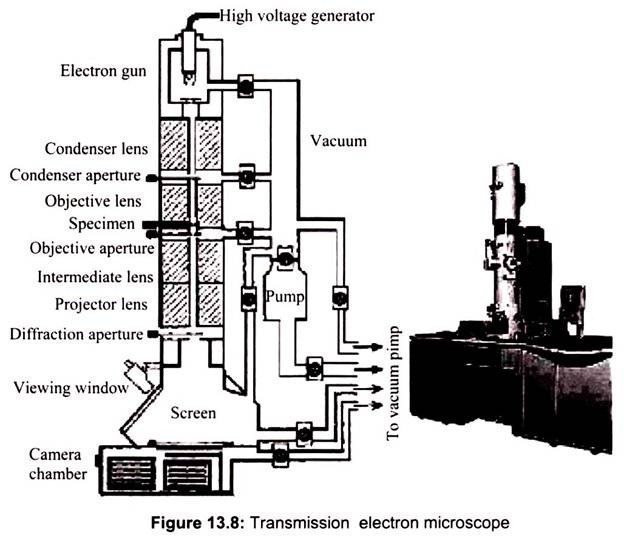
In Transmission electron microscopy, the ray of electrons is produced by a pin-shaped cathode heated up by current. The electrons are collected by the anode. The acceleration voltage is between 50 and 150 kV. The higher it is, the shorter are the electron waves and the higher is the power of resolution. But this factor is hardly ever limiting. The power of resolution of electron microscopy is usually restrained by the quality of the lens-systems and especially by the technique with which the preparation has been achieved. Modern gadgets have powers of resolution that range from 0.5 – 10 nm. The useful magnification is therefore more than 1,000,000X. In transmission electron microscopy the two dimensional image of a thin section of a specimen is obtained (Fig. 13.8).
Preparation in Transmission Electron Microscopy (TEM):
Transmission Electron Microscopy (TEM) allows visualization of fine cellular structures of nanometer-size.
(a) Fixation:
The specimen, a piece of biological tissue of a few millimeters or single cell, is fixed with chemical products (e.g. glutaraldehyde) or cold (liquid propane at – 90°C, for physical fixation). Fixation is done to preserve the fine structure in the cells in a state as close as possible to the living state and to make the cells permeable for the components required in the next steps of preparation.
(b) Rinsing and Staining:
After fixation the next step is rinsing away of the fixative. The material is treated with heavy metal compounds (osmiumtetroxide, uranylacetate or potassium permanganate) that bind preferably to certain regions like lipid-rich membranes of organelles, DNA-clusters in the cell nucleus, and protein-rich structures like cytoskeletal elements. Such metal-compounds have the property to reflect electrons so that labeled structures appear as dark areas in the electron microscopic view.
(c) Dehydration:
To be able to cut extremely thin sections (60-90 nm) that keep their consistency and yet allow electrons to pass the stained samples are imbedded in resins (plastics). As most of these resins are hydrophobic, it is necessary to remove all water from the sample through wash steps of increasing ethanol or acetone concentration, followed by final washes in another non-polar substance like propylene oxide.
(d) Imbedding in Resin:
Later the material is gradually infiltrated with the still unpolymerized resin (e.g. methacrylates, polyester and epoxy-resins, acryls, polyethyleneglycol and others) desolved in the non-polar and volatile transition medium that evaporates. Trimming of the block of resin and ultra-thin sectioning: Sections with a thickness of about 70 nm can only be cut with special knifes of cleaved glass of high purity made with a glass-knife maker (which breaks glass in triangles with extremely sharp edges) or with a diamond knife. The cutting is done with an ultra-microtome (a precision cutting instrument) with numerous setting possibilities.
(e) Picking up Sections on a Grid:
Water in a tiny container behind the knife contributes to lubrification of the cut edge. Sections float on that surface (in air they would easily become electrostatic and jump aside or be blown away). The thickness of the section can be estimated with quite high accuracy from the reflection color of the floating section. These very fragile rows of trapezoid-shaped sections can be lift up like with a spoon from the water surface onto a so-called grid. Grids are later inserted into the electron microscope with help of a rod-shaped holder.
iii. Scanning Electron Microscopy (SEM):
The SEM is a microscope that uses electrons instead of light to form an image, in the early 1950s. It uses a focused beam of high-energy electrons to generate a variety of signals at the surface of solid specimens. The signals that derive from electron-sample interactions reveal information about the sample including external morphology (texture), chemical composition, crystalline structure and orientation of materials making up the sample. Areas ranging from approximately 1 µm to 5 microns in width can be imaged in a scanning mode using conventional SEM techniques (magnification ranging from 20X to approximately 30,000X, spatial resolution of 50 to 100 nm).
The SEM has allowed researchers to examine a much bigger variety of specimens. The scanning electron microscope has many advantages over traditional microscopes. The SEM has a large depth of field, which allows more of a specimen to be in focus at one time. The SEM also has much higher resolution, so closely spaced specimens can be magnified at much higher levels. As the SEM uses electromagnets rather than lenses; it has much more control on the degree of magnification. All of these advantages, as well as the actual strikingly clear images make the scanning electron microscope one of the most useful instruments in research today.
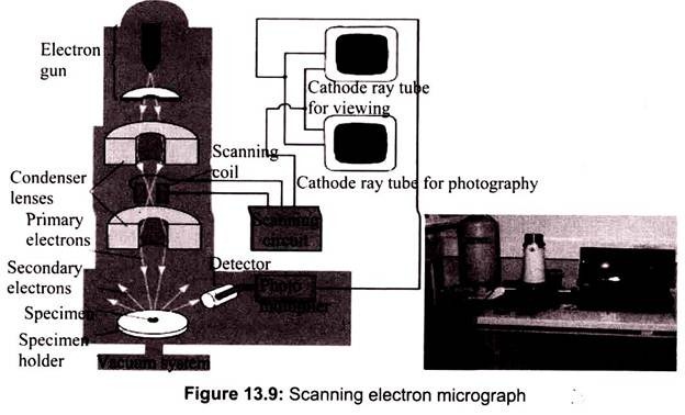
A beam of electrons is produced at the top of the microscope by an electron gun. The electron beam follows a vertical path through the microscope, which is held within a vacuum. The beam travels through electromagnetic fields and lenses, which focus the beam down toward the sample. Once the beam hits the sample, electrons and X-rays are ejected from the sample. In SEM the image is formed from secondary electrons that have been dislocated at the surface of the scanned sample by bombarding primary electrons from the electron gun. Those ejected electrons are captured by a detector and the information is converted into an electric signal, amplified and digitalized.
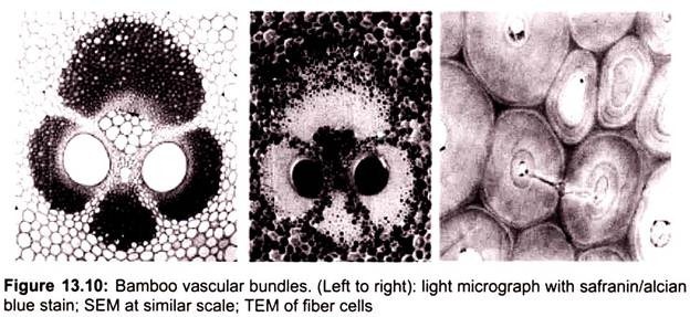
The result is a topographical image of the surface of the object. Besides secondary electrons, radiation in particular X-rays and cathodoluminescence are produced upon interaction of atoms in the surface layer of the sample with the primary electron beam. These emission signals, which contain information among others on the element composition of the upper layer, can be received by selected detectors and convert them into signal that is sent to a screen similar to television screen (Fig. 13.10).
Sample preparation can be minimal or elaborate for SEM analysis, depending on the nature of the samples and the data required. Minimal preparation includes acquisition of a sample that will fit into the SEM chamber and some accommodation to prevent charge build -up on electrically insulating samples. Most electrically insulating samples are coated with a thin layer of conducting material, commonly carbon, gold, or some other metal or alloy. The choice of material for conductive coatings depends on the data to be acquired: carbon is most desirable if elemental analysis is a priority, while metal coatings are most effective for high resolution electron imaging applications, because the SEM utilizes vacuum conditions and uses electrons to form an image, special preparations must be done to the sample. All water must be removed from the samples because the water would vaporize in the vacuum.
The SEM is routinely used to generate high-resolution images of shapes of objects and to show spatial variations in chemical compositions. It is also widely used to identify phases based on qualitative chemical analysis and/or crystalline structure. Backe scattered electron images can be used for rapid discrimination of phases in multiphase samples. SEMs equipped with diffracted backscattered electron detectors can be used to examine microfabric and crystallographic orientation in many materials.
SEM has some limitations such as the samples must be solid and they must fit into the microscope chamber. Maximum size in horizontal dimensions is usually on the order of 10 cm; vertical dimensions are generally much more limited and rarely exceed 40 mm. For most instruments samples must be stable in a vacuum on the order of 10-5-10-6 torr. An electrically conductive coating must be applied to electrically insulating samples for study in conventional SEM’s, unless the instrument is capable of operation in a low vacuum mode.
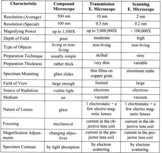
Table 13.1: Comparison of Different types of microscope
